Electrical installation 2 - 39, Wiring the pg-w2 – Yaskawa F7 Drive User Manual User Manual
Page 66
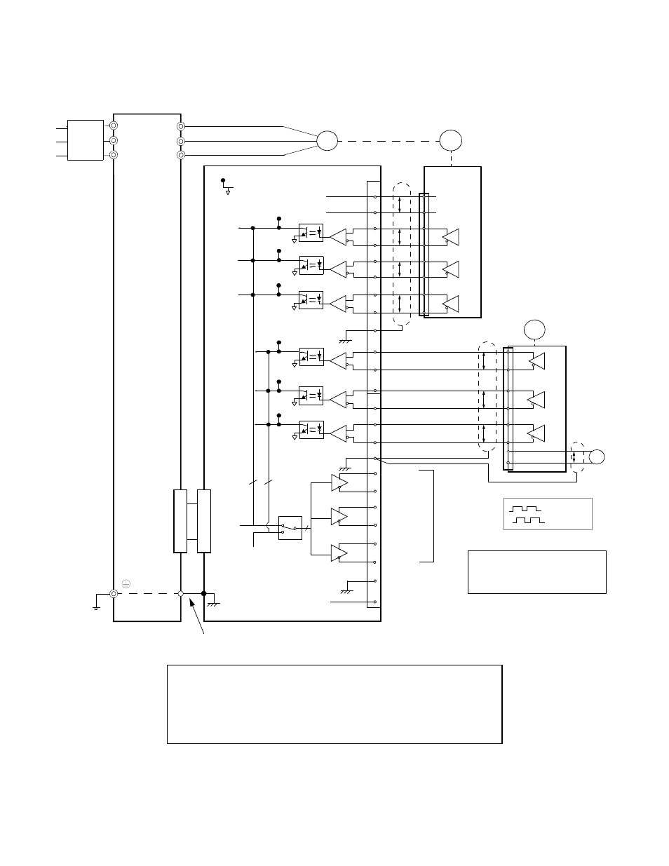
Electrical Installation 2 - 39
Wiring the PG-W2
Wiring examples are provided in Fig 2.23 for the PG-W2.
Fig 2.23 PG-W2 Wiring
R/L1
S/L2
T/L3
M
U/T1
V/T2
W/T3
Drive
PG-1
1
2
3
4
5
6
7
8
9
10
11
12
13
14
15
16
17
18
19
20
21
22
23
24
IP12
*
IG12
(+12V)
(0V)
12V
0V
P
P
P
P
P
P
P
TP1
(E)
12V
0V
P
+
Pulse A
Pulse B
Pulse Z
Pulse
IG5
(0V)
PG-2
4CN
4CN
12
TP3
TP7
TP6
TP5
TP4
TP8
3
Pulse
Out 1
3
Pulse A1
Pulse B1
Pulse Z1
Pulse A2
Pulse B2
Pulse Z2
TP2
Notes:
* Power supply for PG-1 (from PG-W2).
** PG-2 requires external power supply.
Pulse A
Pulse B
Ground wire
**
3
Pulse
Out 2
(E)
-
12V
Monitor
Outputs
(E)
(E)
PG-W2
Branch
Circuit
Protection
•
Shielded twisted-pair wires must be used for signal lines.
•
Do not use the PG-W2's power supply for anything other than the pulse generator (encoder).
Using it for another purpose can cause malfunctions due to noise.
•
The length of the pulse generator's wiring must not be more than 100 meters.
•
Do not use PG-W2 to supply both PG units.