Electrical installation 2 - 36, Pg-d2, Wiring the pg-d2 – Yaskawa F7 Drive User Manual User Manual
Page 63
Electrical Installation 2 - 36
PG-D2
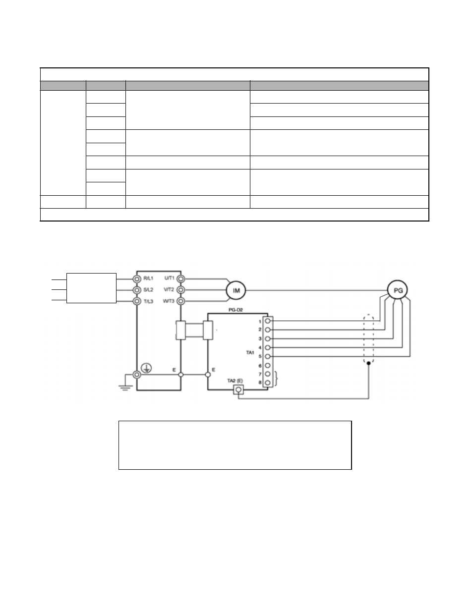
The terminal specifications for the PG-D2 are given in Table 2.20.
Wiring the PG-D2
Wiring examples are provided in Fig 2.21 for the PG-D2.
Fig 2.21 PG-D2 Wiring
Table 2.20 PG-D2 Terminal Specifications
Terminal
No.
Contents
Specifications
TA1
1
Power supply for pulse generator
12Vdc (±5%), 200mA max.*
2
0Vdc (GND for power supply)
3
5Vdc (±5%), 200mA max.*
4
Pulse input terminals
Line driver input (RS-422 level)
Maximum response frequency: 300kHz
5
6
Common terminal
-
7
Pulse monitor output terminals
Line driver output (RS-422 level)
8
TA2
(E)
Shield connection terminal
-
* 5Vdc and 12Vdc cannot be used at the same time.
Drive
Power supply 0Vdc
Power supply +5Vdc
Pulse input + (A phase)
Pulse input - (A phase)
Pulse monitor output
R/L1
S/L2
T/L3
Branch
Circuit
Protection
Power supply +12Vdc
4CN
4CN
•
Shielded twisted-pair wires must be used for signal lines.
•
Do not use the PG-D2's power supply for anything other than the pulse generator (encoder).
Using it for another purpose can cause malfunctions due to noise.
•
The length of the pulse generator's wiring must not be more than 100 meters.