System connection map, Traffic advisor indicators output indicators, Cencom led indicators – Whelen CCSRN3 User Manual
Page 10: Manufactured in america, Sapphire, Led indicators, Page 10
Page 10
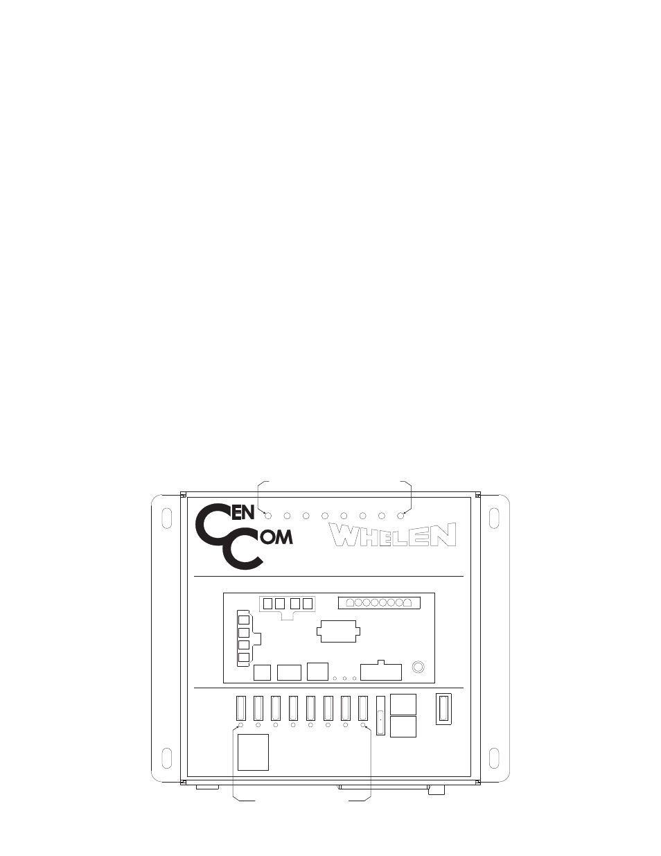
CenCom LED Indicators
+
-
+
-
40A
OUTPUT
WC
LIGHTBAR
CTRL
HEAD
OUTPUT
2
20A
20A
MAIN
POWER
20A
OUTPUT
3
20A
OUTPUT
4
10A
OUTPUT
5
10A
OUTPUT
6
10A
OUTPUT
7
10A
T/A
FUSE
20A
OUTPUT
7
10A
OUTPUT
10A
POSITION
DRY
CONTACT
POSITION
OUTPUT 1
40A
1
2
1
3
20A
OUTPUT
ERR
H S
USB
L
WC POW
PA
SYSTEM
I/O
10A OUTPUTS
SYSTEM CONNECTION MAP
4
5
6
7
C NC NO
TRAFFIC
ADVISOR
MANUFACTURED IN AMERICA
®
- 20 -
- 20 -
- 20 -
- 20 -
- 20 -
- 10 -
- 10 -
- 10 -
- 10 -
- 10 -
SAPPHIRE
TA1
TA2
TA3
TA4
TA5
Traffic Advisor Indicators
Output Indicators
TA6
TA7
TA8
LED Indicators
LED Indicators provide valuable information regarding the operational state of your CenCom system. There are 3 different sets of
LED’s for 3 different CenCom functions.
Traffic Advisor Indicators - These LEDs represent Traffic Advisor Output 1 (TA1) thru Traffic Advisor Output 8 (TA8). When a given
output is active or flashing, the state of its corresponding indicator will be one of the following, based on the condition of that particular
output:
On (steady) - Indicates the output is active and not flashing (normal).
On (flashing) - Indicates the output is active and flashing (normal).
Off - Indicates the output is shorted. Turn the CenCom system off, locate and remove the short. Restore power to the system
and activate the output to confirm its proper operation.
Output Indicators - These represent Outputs 1 thru 7. Each indicator is located directly adjacent to the fuse for that output.When a
given output is active, the state of its corresponding indicator will be one of the following, based on the condition of that particular
output:
On - Indicates the output is active (normal).
Off - Indicates the output is shorted. Turn the CenCom system off, locate and remove the short. Replace the fuse for that output
(with correct amperage rating) and restore power to the system. Activate the output to confirm its proper operation.
WC Diagnostic Indicators - These indicators provide the following diagnostic information about the CenCom system:
ERR (Error) LED
Steady
CenCom Controller Bus is set to OFF. Check Interface Box.
Off
No Error
Single Flash
Bad CenCom connection. Check lightbar I/O or Interface Box for proper operation.
Double Flash
Error Control Event. Check lightbar I/O.
WC (CenCom Serial Data Bus) LED
Steady
Good communication received from lightbar.
Off
Check power LED; If Off, turn on controller. If On, check connections.
Fast Blink
Pre-operational State (Boot-up)
Single Flash
Bad CenCom connection or CenCom off. Check lightbar I/O or interface box for proper operation.
POW (Power) Status LED
Steady
CenCom system is On
Off
CenCom system is Off.