Top view, Front view, Input expansion table pa volume adjustment – Whelen CCSRN3 User Manual
Page 9: Radio repeat volume adjustment, Cencom module fuses, Input expansion module (optional), Control heads, Page 9, Isolated relay (outlet 8)
Page 9
Input Expansion Table
PA Volume Adjustment
Locate the PA adjustment potentiometer on the right side of the
CenCom module. Using a small, flat-blade screwdriver, set the
potentiometer to its middle position. With the CenCom™ system on,
activate the PTT (Push To Talk) feature on the optional microphone.
Adjust the potentiometer until a satisfactory PA volume level is achieved
using a normal speaking voice.
Radio Repeat Volume Adjustment
To Adjust the Radio Repeat Levels: Before placing this unit into service,
the Radio Repeat output volume must be adjusted to satisfactory
operating levels. To adjust this level, a small, flat-blade screwdriver is
needed. Locate the Radio Repeat adjustment potentiometer on the
right side of the CenCom module. Set the volume of the vehicle’s two-
way radio to its normal operating level. Press the RAD button on the
control head to activate Radio Repeat. As incoming transmissions are
received, adjust the Radio Repeat potentiometer to set the desired
level. Turn the potentiometer clockwise to increase the level and
counter-clockwise to decrease the level.
CenCom Module Fuses
For ease of access, all of the amp/relay module fuses are accessible from
outside the case.
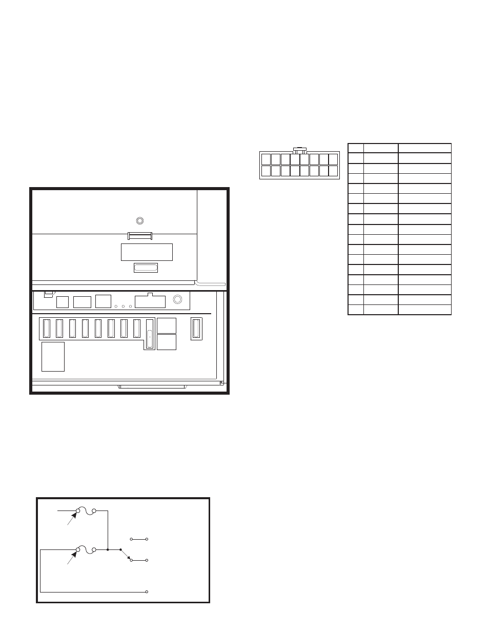
Isolated Relay (Outlet 8)
The position of the Output 8 fuse determines the function of the Brown,
Red and Orange wires. When the fuse is in Position 1, these wires act as
a Isolated 10 Amp Relay. When the fuse is in Position 2, the Brown and
Red wires act as Outlet #8. Refer to the schematic shown for the
electronic properties of this circuit.
Amp/relay Module
Fusing Information
Isolated Relay (Outlet
8)
F1
(POS.1)
Common (Orange/21)
Normally
Closed (Red/22)
Normally
Open (Brown/23)
Fuse in
Dry-Contact
Position
Fuse in
10 Amp Outlet
Position
F1
(POS.2)
+12VDC
LIGHTBAR
CTRL
HEAD
OUTPUT
2
20A
20A
MAIN
P
20A
OUTPUT
3
20A
OUTPUT
4
10A
OUTPUT
5
10A
OUTPUT
6
10A
OUTPUT
7
10A
T/A
FUSE
20A
OUTPUT
7
10A
OUTPUT
10A
POSITION
DRY
CONTACT
POSITION
OUTPUT 1
40A
ERR
H S
USB
L
WC POW
PA
SYSTEM
I/O
- 20 -
- 20 -
- 20 -
- 20 -
- 20 -
- 10 -
- 10 -
- 10 -
- 10 -
- 10 -
Top
View
SIREN FUSE
20A
- 20 -
Front
View
Positive Input 2
Positive Input 8
RED
GREY
2
8
3
9
13
5
11
15
4
10
14
6
12
16
Positive Input 6
Negative Input 4
Negative Input 8
BLUE
WHT/YEL
WHT/GRY
GREEN
WHT/ORG
WHT/VIO
ORANGE
WHT/BRN
WHT/GRN
YELLOW
WHT/RED
WHT/BLU
Positive Input 4
Negative Input 2
Negative Input 6
Positive Input 5
Negative Input 3
Negative Input 7
Positive Input 3
Negative Input 1
Negative Input 5
1
7
BROWN
VIOLET
COLOR
FUNCTION
Positive Input 1
Positive Input 7
WIRE CHART
WIRE SIDE VIEW
POS
1
9
2
3
4
5
6
7
8
10
11
12
13
14
15
16
Input Expansion Module (optional)
The optional input expansion module enables up to eight (8) non-CenCom
vehicle components and/or equipment to be integrated into the CemCom/
Cantrol network.
As shown in the tables below, connect the input wire of the desired device
to the appropriate wire. For example, if the device in question requires a
Positive input signal, that input wire would be connected to the BROWN
expansion module pigtail wire. In this example, that device would be
recognized as “INPUT 1” by the Cantrol system. However, if that device
requires a Negative input signal, that input wire would be connected to the
WHT/BRN expansion module pigtail wire. Note that this device would be
recognized as “INPUT 1” by the Cantrol system.
Control Heads....
A wide variety of control heads are available for use with this system.
The specific function of any button, slide switch or rotary knob can be
customized via the CenCom configuration software program. The
following pages will present all of the available control heads and their
default operating configuration.