Wiring, System power (items 43-46), Ignition sense (item 38) – Whelen CCSRN3 User Manual
Page 8: Outputs, Siren speaker (items 30 & 37), Radio rebroadcast (items 29 & 36), Backlighting (item 31), Park-kill (optional) (item 26), Hands-free siren (items 33 & 35) (optional), Hands-free transfer relay
Page 8
Wiring
WARNING! All customer supplied wires that connect to the positive
terminal of the battery must be sized to supply at least 125% of the
maximum operating current and FUSED at the battery to carry that
load. DO NOT USE CIRCUIT BREAKERS WITH THIS PRODUCT! (see
wire chart on page 14).
NOTE: Item numbers reference the illustration found on page 12.
IMPORTANT!
Wires connecting to the Amp/Relay Module have the
proper terminals pre-installed. If the customer needs to re-terminate
these wires for any reason, the proper tool MUST be used to insure
proper crimping.
System Power (Items 43-46)
1.
Locate the 4-position Molex™ connector (items 43 thru 46).
2.
Using appropriately sized wire, extend the two RED wires (45 & 46)
to the Positive (+) battery terminal. Fuse each wire independently @
50 Amps. DO NOT install these fuses until the wiring for the entire
system has been completed.
3.
Using appropriately sized wire, extend the two BLACK wires (43 &
44) to the vehicle’s chassis ground (typically adjacent to the battery).
4.
Complete the connections and plug the connector into the
CenCom™ module.
Ignition Sense (Item 38)
1.
Locate the RED/BLK wire at Connector C, Pin 14.
2.
Connect this wire to the ignition switch to allow the CenCom™
system to be turned off with the ignition switch. See Shutdown
Module for optional connection
Outputs
CenCom™ offers the following outlets: (1) 40 amp, (2) 20 amp, (5) 10 amp
and (4) 0.25 amp. See page 12 for more information.
Siren Speaker (Items 30 & 37)
1.
Route the ORANGE and BROWN 16 gage wire (included) from
Connector C, Pins 6 &13, to the siren speaker.
2.
Connect ORANGE wire to the WHITE speaker wire (speaker high).
3.
Connect BROWN wire to BLACK speaker wire (speaker low).
NOTE: For dual speaker installation, connect the second speakers wires
to the same destinations as the first speakers wires (see page 11).
Radio Rebroadcast (Items 29 & 36)
Two (2) BLU wires are used to connect your two-way radio’s external
speaker for radio rebroadcast. This is an optional connection and will not
effect the other operations. Note: Radio rebroadcast will NOT work with
amplified remote speakers! If your remote speaker is amplified (i.e.:
contains a power amp circuit in the speaker assembly), do not enable the
radio rebroadcast feature.
1.
Locate the two wires that connect the external speaker to the two-
way radio, cut one of them and splice one of the BLU wires into this
circuit.
2.
Cut the remaining speaker wire and splice the remaining BLU wire
into this circuit.
Backlighting (Item 31)
Note: The CenCom backlight circuit has been designed to accept any of
the following:
•
0 VDC input (off)
•
12VDC input (on)
•
A Pulse Width Modulated (PWM) input with a range of 0% - 100%
duty cycle @ 100Hz (i.e. dimmer circuit).
1.
Route the WHT/BLK wire (included) from Connector C, Pin 7, to the
vehicle’s marker light circuit.
2.
Splice this wire into this circuit to enable the control head backlighting
to be active whenever the vehicle’s marker light is active.
Programmable Inputs (Item 25, 26, 32, 33)
There are 4 programmable inputs in the CenCom system. The output
signal line from devices such as a K-9 temperature sensor may be
connected to these inputs. Two of these inputs (items 26 & 33) are
designated for use when the Park-Kill or Hands-Free system options are
used (see below).
Park-Kill (Optional) (Item 26)
CAUTION! Always consult your vehicle’s technical manual before
altering your vehicle’s wiring. Wiring modifications may compromise
your vehicle’s safety and/or performance. Use of the Park-Kill option
may require the installation of the Whelen WPKM1 Park-Kill module.
Consult your vehicle’s technical manual before using this feature.
Using appropriately sized wire, extend and connect the WHT/ORN wire
from Connector C, Pin 2, to the vehicle’s transmission neutral safety
switch signal wire. NOTE: For programming purposes, it is necessary to
know whether this signal wire is switching the positive or negative side of
the circuit.
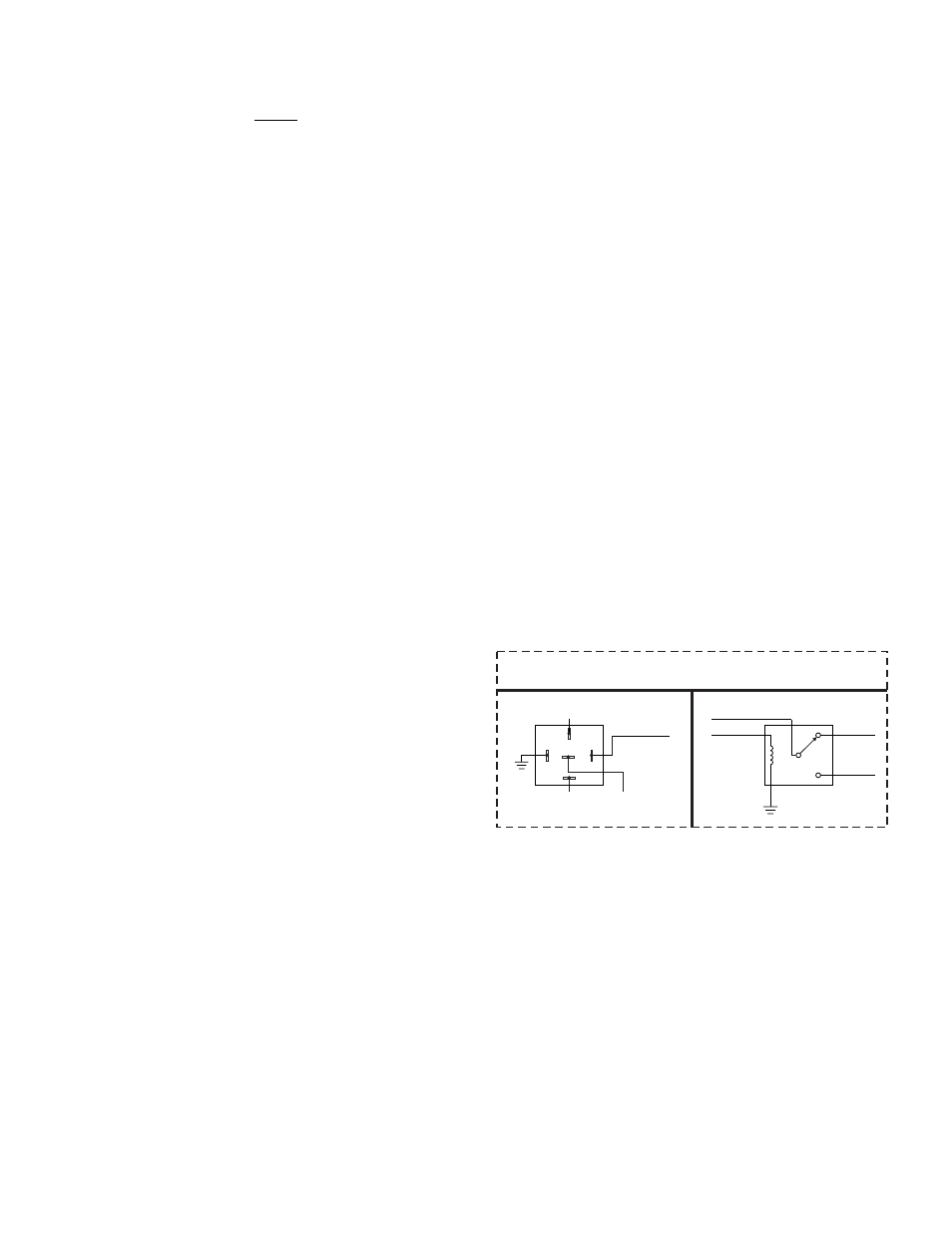
Hands-Free Siren (Items 33 & 35) (Optional)
1.
Using a customer supplied relay capable of handling the current of
your vehicle horn, connect as shown below.
Hands-Free Transfer
Relay
Horn Ring
Transfer Relay
(Customer Supplied)
Bosch™
Style
(Tyco-P&B P/N:VF4-45F11)
Generic
Style
To Vehicle
Car Horn
N.O.
N.C.
From Vehicle
Horn Relay
To
Outlet #12
(Item 35)
To
Input #4
(Item 33)
From Vehicle
Horn Relay
To Vehicle
Car Horn
To
Input #4
(Item 33)
To
Outlet #12
(Item 35)
30
87A
85
86
87