Cencom™ module input/output identification – Whelen CCSRN3 User Manual
Page 12
Page 12
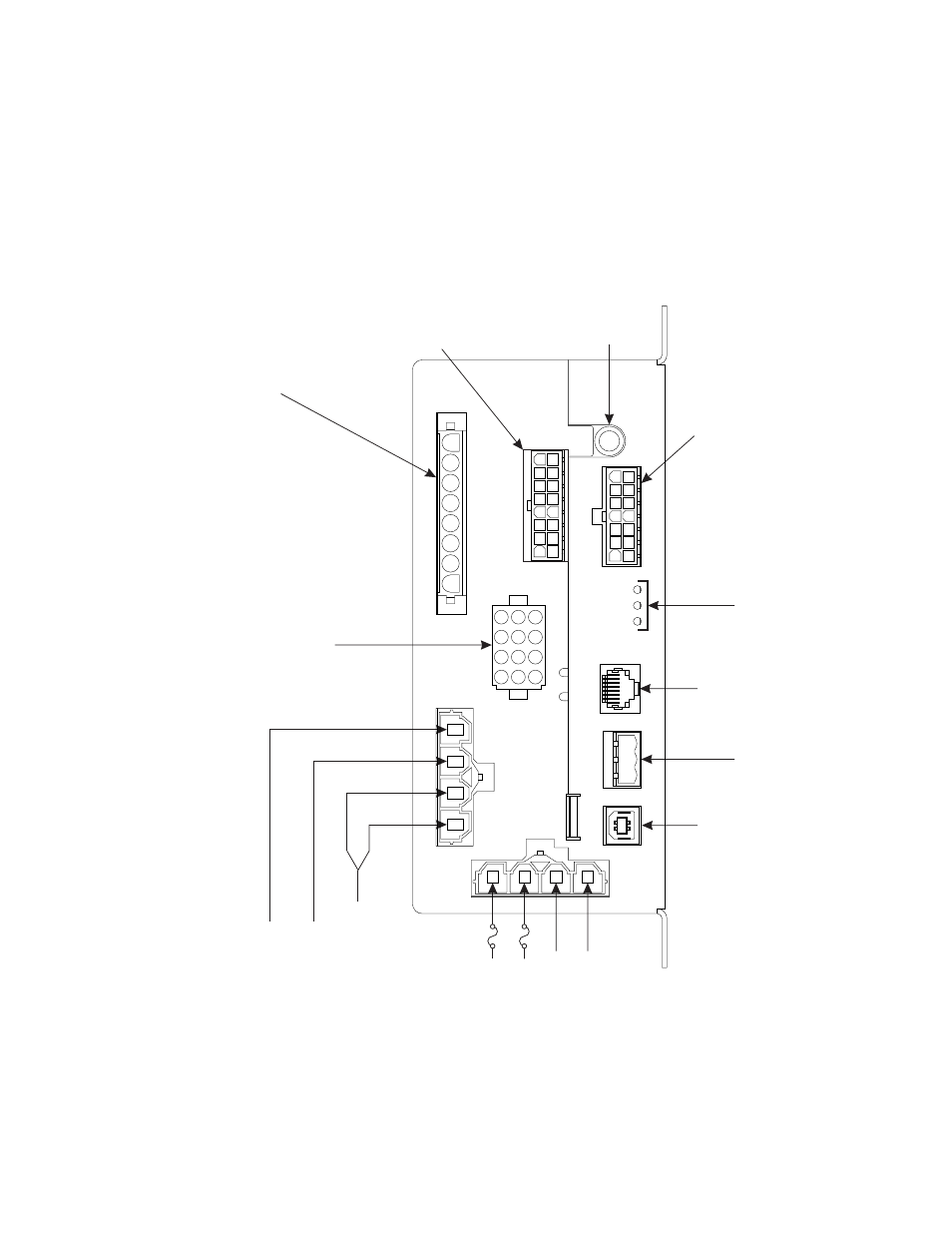
Amp Relay Module I/O
Wiring ID
16.
PIN 1 - Output #4
(10A
/ GR
Y)
17.
PIN 2 - Output #5
(10A
/ VIO)
18.
PIN 3 - Output #6
(10A
/ BLU)
19.
PIN 4 - Output #7
(10A
/ GRN)
20.
PIN 5 - Unused
21.
PIN 6 - Output #8
(Dry Contact Relay - Common)
22.
PIN 7 - Output #8
(
Normally Closed)
23.
PIN 8 - Output #8
(
Normally Open)
Dry Contact Relay -
Dry Contact Relay -
1.
Output #1
(40A
/ WHT)
40A
Max. T
otal
20A
Max. Each
2.
Output #2
(20A
/ BLU)
24.
Microphone Port
39.
Diagnostic LEDs
41.
WC Lightbar Port
PIN 1 - CAN
A
(Green)
PIN 2 - Shield (Bare)
PIN 3 - CAN B (Grey)
40.
Control Head
42.
USB Port
46.
System Power
50A
50A
45.
System Power
44.
System Ground
43.
System Ground
3.
Output #3
(20A
/ GRN)
4.
PIN 1 -
5.
PIN 2 -
6.
PIN 3 -
7.
PIN 4 -
8.
PIN 5 -
9.
PIN 6 -
10.
PIN 7 -
1
1
.
PIN 8 -
12.
PIN 9 - (+) Lamp V
oltage (WHT)
13.
PIN 10 - No Connection
14.
PIN 1
1
T/A
Lamp #1 (BRN)
T/A
Lamp #2 (RED)
T/A
Lamp #3 (ORN)
T/A
Lamp #4 (YEL)
T/A
Lamp #5 (GRN)
T/A
Lamp #6 (BLU)
T/A
Lamp #7 (VIO)
T/A
Lamp #8 (GR
Y)
- No Connection
15.
PIN 12 - No Connection
.
PIN 1
.
PIN 2
.
PIN 3
.
PIN 4
.
PIN 5
.
PIN 6
.
PIN 7
.
PIN 8
33.
PIN 9
Logic Input 4 / Horn Ring +/-
WHT/YEL
34.
PIN 10
Output #1
1 (250 mA)
ORG
.
PIN 1
1
25
Logic Input 1 +/-
WHT/BRN
26
Logic Input 3 +/-
WHT/ORG
27
Output #10 - 250 mA
RED
28
Output #9 - 250 mA
BRN
29
Radio
BLU
30
Siren Speaker
ORG (16
A
WG)
31
Backlight Input 12VDC
WHT/BLK
32
Logic Input 2 +/-
WHT/RED
35
Output #12 / Horn T
ransfer (250 mA)
YEL
36.
PIN 12
Radio
BLU
37.
PIN 13
Siren Speaker
BRN (16
A
WG)
38.
PIN 14
Ignition +12VDC
RED/BLK
CenCom™
Module
Input/Output Identification
1
2
3
4
567
8
1
2
3
4
5
6
7
8
9
10
11
12
13
14
15
16
1
8
2
9
3
10
4
11
5
12
6
13
7
14
12
9
6
3
1
1
852
1
0
741
123
PIN 1 (BRN)
-
Expansion Input #1 (POS)
PIN 2 (RED)
-
Expansion Input #2 (POS)
PIN 3 (ORG)
-
Expansion Input #3 (POS)
PIN 4 (YEL)
-
Expansion Input #4 (POS)
PIN 5 (GRN)
-
Expansion Input #5 (POS)
PIN 6 (BLU)
-
Expansion Input #6 (POS)
PIN 7 (VIO)
-
Expansion Input #7 (POS)
PIN 8 (GR
Y)
-
Expansion Input #8 (POS)
PIN 9 (WHT/BRN)
-
Expansion Input #1 (NEG)
PIN 10 (WHT/RED)
-
Expansion Input #2 (NEG)
PIN 1
1
(WHT/ORG)
-
Expansion Input #3 (NEG)
PIN 12 (WHT/YEL)
-
Expansion Input #4 (NEG)
PIN 13 (WHT/GRN)
-
Expansion Input #5 (NEG)
PIN 14 (WHT/BLU)
-
Expansion Input #6 (NEG)
PIN 15 (WHT/VIO)
-
Expansion Input #7 (NEG)
PIN 16 (WHT/GR
Y)
-
Expansion Input #8 (NEG)
Note:
The optional Input Expansion Module is
programed using the CenCom Software
program.