Installation – Whelen CCSRN3 User Manual
Page 4
Page 4
Installation
CenCom Module
1.
Locate a suitable mounting location. A dry, cool compartment is a
good choice.
2.
Position the CenCom module on the proposed mounting location.
Using an awl or similar tool, scribe the mounting surface where the
mounting holes are to be drilled. Make sure that this mounting area
allows sufficient ventilation for the CenCom module’s air vents and
fans.
Caution:
As mounting the CenCom module will require drilling, it
is absolutely necessary to make sure that no other vehicle
components could be damaged in the process. Check both sides of
the mounting surface before starting. If damage is likely, select a
different mounting location.
3.
Remove the module from its mounting area, and using a drill bit sized
for a #10 sheet metal screw, drill a hole in each of the areas scribed
in the previous step.
4.
Return the module to its mounting location. Using #10 x 3/4” sheet
metal screws (provided), secure the module onto its mounting
surface. Be sure to install a #10 internal tooth lock washer (included)
onto each mounting screw. IMPORTANT: The CenCom module case
must be either mounted on, or grounded to the vehicle chassis.
Control Head
The following sections will outline the varrious mounting styles available
for the assorted CenCom control heads. The applicable mounting styles
for each control head are listed on pages 5 thru 7.
Regardless of the style selected, be sure to observe the air bag
warning on the cover of this manual.
Caution: As mounting the control head will require drilling, it is
absolutely necessary to make sure that no other vehicle components
could be damaged in the process. Check both sides of the mounting
surface before starting. If damage is likely, select a different
mounting location.
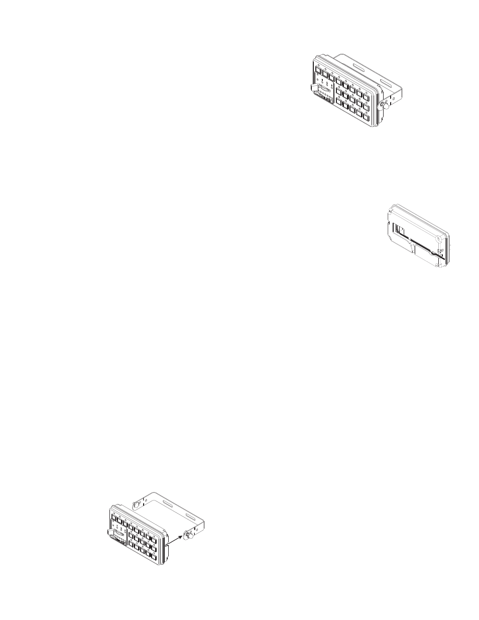
Bail Strap Mount
1.
Position the bail strap in the selected mounting location. Using an awl
or other suitable tool, scribe the surface where the mounting holes
are to be drilled.
2.
Drill the mounting holes in the areas scribed in step 1. The size of the
drill bit should be determined by the size of the mounting hardware (#10
sheet metal screw) and thickness of the mounting surface.
3.
Using hardware provided (#10 x 3/4” sheet metal screw & #10
internal tooth lockwasher), secure the bail strap to the mounting
location.
Note:
There are 3 sets of holes on the bail strap for positioning
the control head at 3 different heights.
4.
With the bail strap in place, insert the #10 x 3/8” hex head bolt into
the assembly hole from the inner side of the bail strap as shown.
Bail
Strap
Mount
Control head
shown for
reference-only
5.
Place the #10 internal-tooth lock washer and the acorn nut on the
protruding bolt on the outer side of the bail strap. Loosely secure the
acorn nut to the hex head bolt.
Now slide the control head onto the bolt heads. Once it is in the position
that the customer has chosen, and the control head has fully engaged the
bolt heads, tighten the acorn nuts until the unit is firmly secured.
A third pair of mounting holes are provided that will enable the control
head to be located much closer to the bail strap than the other pairs allow.
If this closer location is used, the tips of the bail bracket may be broken off
at the notches shown.
Route the control head cable (provided) from the
CenCom module to the designated mounting
location. Plug this cable securely into the rear of
the control head. Be sure to route the cable
through either of the two recessed pathways
(shown here).This will prevent the cable from
being accidentally disconnected or pinched by
the control head.
Havis Console Mount
The Havis Console mounting kit includes all the necessary hardware
needed to secure the control head to the mounting bracket for installation
on a Havis Console. Please refer to the manual included with your console
for specific information on securing the control head/mounting bracket
assembly onto the console.
For installation into consoles by other manufacturers, a control head
bracket designed for your console must be obtained from the console
manufacturer.
Microphone Mount
A 1/4” microphone port is provided on the front of the Amp/Relay module.
After plugging the microphone cord into the microphone port, secure the
cord using the cable clamp and #8 x 3/8” machine screw (included with
microphone kit).
If the optional 20’ extension cord is used, install this cord as outlined
above. Install the mic plug bracket (included with kit) in the desired area
using #8 x 1/2” hardware (included). Route the cord to the plug bracket,
install the cable end thru the bracket hole and fasten using the hex nut
provided. Secure the cord to the bracket using the cable clamp, #8 x 3/8”
machine screw and lock washer.
Plate Mount (6 Button w/Slide Switch Only)
Secure the plate to the back of the control head using the #4 x 1/4”
hardware provided. Position the control head/plate assembly onto the
mounting surface and confirm that this location will not interfere with any
existing components or prevent safe operation of the vehicle.
With the control head in place, mark the two mounting holes. Remove the
control head/plate assembly and drill the mounting holes using a bit sized
for #6 sheet metal screw. De-burr the mounting holes and secure the
control head/plate assembly using the #6 x 1/2” hardware provided.
Default Control Head Configurations
The default operating configurations for the control heads available for the
CenCom Sapphire are listed in the following section.
Cntrl Head
Cable Strain
Releif