Bandwidth, Slew rate, Rise and fall time effect on accuracy – Amprobe BDM40-UA Bench-Digital-Multimeter User Manual
Page 10
9
Your instrument has a crest factor range of 1.0 to 3.0 at full scale. Going down from full-scale, the crest factor
capability increases from 3.0 to: Full-Scale x 3 (i.e. 6 at half-scale) RMS Value , If an input signal has a crest factor
of 3.0 or less, voltage measurements will not be in error due to dynamic range limitations at full-scale. If the crest
factor of a waveform is not known, and you wish to know if it falls within the crest factor of your meter, measure
the signal with both your meter and an ac coupled oscilloscope. If the rms reading on your meter is 1/3 of the
peak voltage on the waveform or less, then the crest is 3.0. For readings at less than full-scale, use the preceding
formula to determine the maximum crest factor. At half-scale the maximum crest factor is: 2 x 3 = 1
The waveforms in Figure 2 show signals with increasing values of crest factor. As you can see from the series of
waveforms, a signal with a crest factor above 3.0 is unusual.
For an ac coupled pulse train: Crest Factor =
1
)
D
/
1
(
−
Where D = duty cycle or the ratio of pulse width to cycle length. Reversing this formula, we find that your meter
can accurately measure pulse trains at full-scale with a duty cycle above 10% without being limited by crest
factor.
1
(1/D)
3.0
Factor
Crest
−
=
=
:
1
-
(1/D)
9.0
=
:
1/D
10.0
=
Bandwidth
Bandwidth defines the range of frequencies where the response of the voltmeter's amplifiers is no more than 3 dB
down (half-power levels). Your instrument has a bandwidth of greater than 200kHz.
Slew rate
Slew rate is also called the rate limit or the voltage velocity limit. It defines the maximum rate of change of the
output of the amplifiers for a large input signal. Slew rate limitations are not a factor in measuring voltages within
specified frequencies and amplitude limits of this DMM.
Rise and fall time effect on accuracy
The rise and fall time of a waveform are the length of time it takes a waveform to change between the points that
are 10% and 90% of the peak value. When discussing these periods, we'll only mention rise time. Errors due to
rise to fall time can be caused either by bandwidth or slew rate limitations. Slew rate should not affect your
measurement with this DMM.
T
t
0
t
1
DC Level
A
t
1
t
1 +
t
0
100usec
48.25
usec
1.75usec
DC Level
A
1.75usec
50usec
DC Level
DC Level
Ideal
Distortion
Components
Example
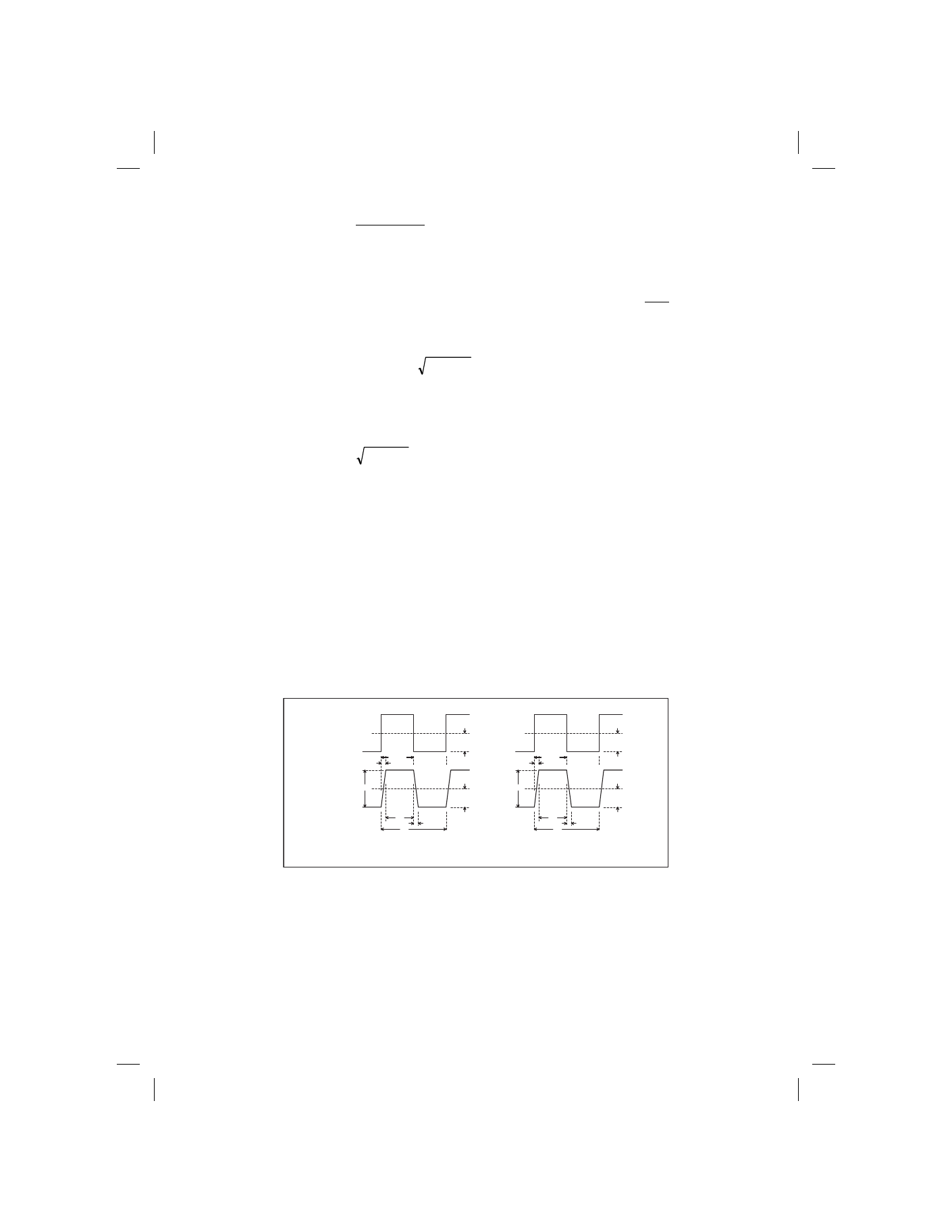
Figure 3 Waveform Distortion
An approximate way of converting bandwidth to rise time limit is to divide 0.35 by the 3 dB down frequency. For
your instrument this will be 0.35/200kHz = 1.75 µsec. The following example will help you calculate errors due to
this limitation when measuring rectangular pulses. These calculations will be rough because ideal waveforms are
used in the analysis.
Ideally, the rectangular pulses would have zero rise and fall time and would be the right angled waveform shown
in Figure 3. In practice, every waveform has a rise and fall time and looks more like the waveform in Figure 3.
When calculating the error caused by the bandwidth of your Instrument, we will assume that the rise and fall time