Amprobe BDM40-UA Bench-Digital-Multimeter User Manual
Page 21
20
14
15
10kHz
50kHz
1.8890 to 1.9110
1.8020 to 1.9980
16
17
20V
19VAC rms
100Hz
10kHz
50kHz
18.890 to 19.110
18.890 to 19.110
18.020 to 19.980
18
19
200V
190VAC rms
100VAC rms
100Hz
10kHz
188.90 to 191.10
99.35 to 100.65
20
21
100V
1000VAC rms
100Hz
1kHz
993.5 to 1006.5
993.5 to 1006.5
Current Test
Use the following procedure to verify proper operation of both the AC and DC mA measurement functions:
1.
Select DC mA, 200µA range.
2.
Connect the calibrator HI amps output to the V-
Ω terminal and the calibrator LO amps output to the
COM terminal.
3.
For each step in Table 6, select the listed range, program the calibrator for the corresponding UUT
input, and verify that the UUT display value lies within the indicated limits.
4.
Set the FUNCTION switch to the AC mA position and select the 20 mA range.
5.
Program the calibrator for a UUT input of 19.000 mA rms at a frequency of 100 Hz.
6.
Verify that the UUT display value lies between 18.890 and 19.110.
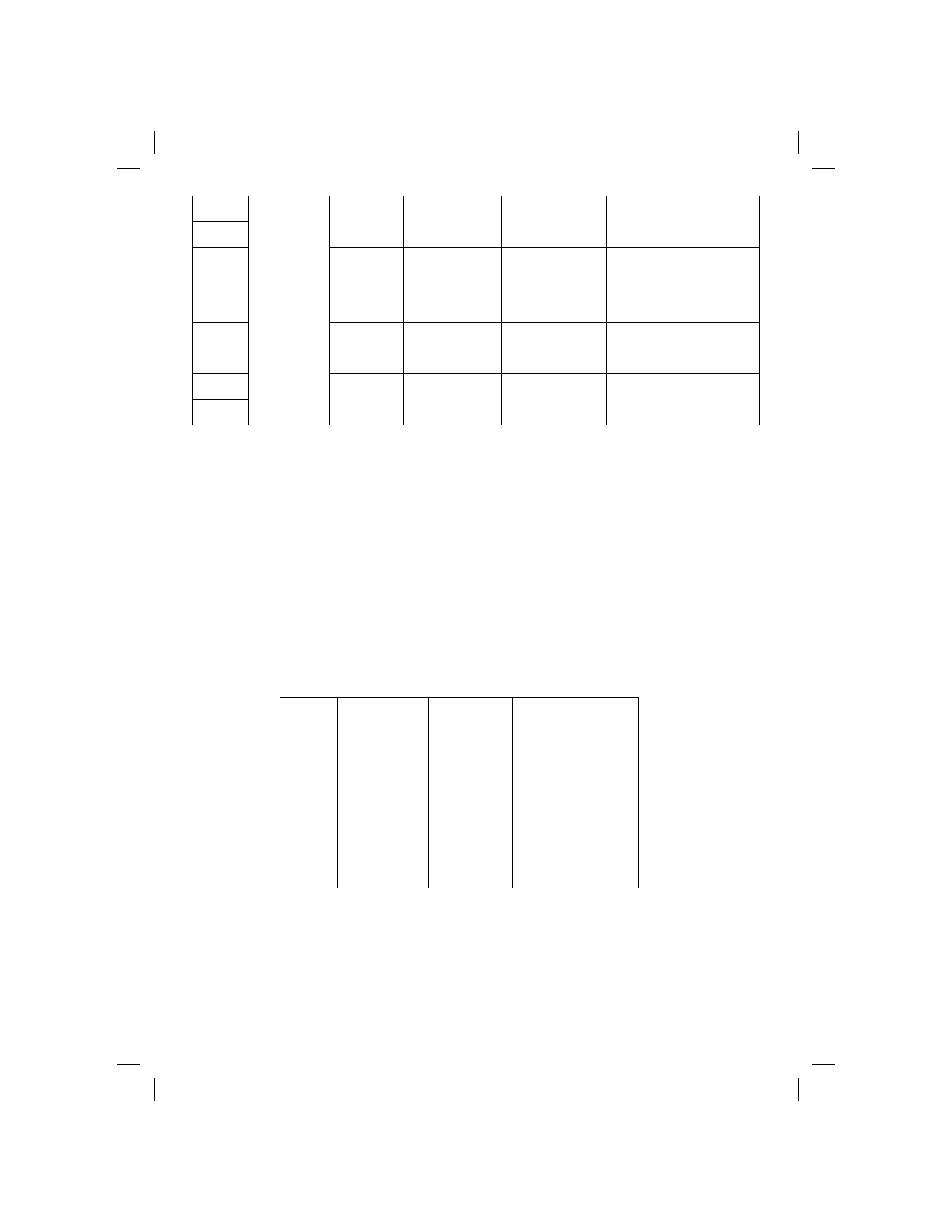
Table 6. Direct Current Test
STEP
SELECT
RANGE
INPUT DISPLAY
READING
1
2
3
4
5
6
200µA
2mA
20mA
200mA
2000mA
20A
190µA
1.9mA
19mA
190mA
1900mA
19A
189.61 to 190.39
1.8961 to 1.9039
18.961 to 19.039
189.61 to 190.39
1894.1 to 1905.9
18.941 to 19.059
Resistance Test
Use the following procedure to verify the accuracy of the k
Ω measurement function:
1.
Select k
Ω, 200Ω range.
2.
Connect the calibrator HI ohms output to the V-
Ω terminal and the calibrator LO ohms output to the
COM terminal.