Amprobe BDM40-UA Bench-Digital-Multimeter User Manual
Page 20
19
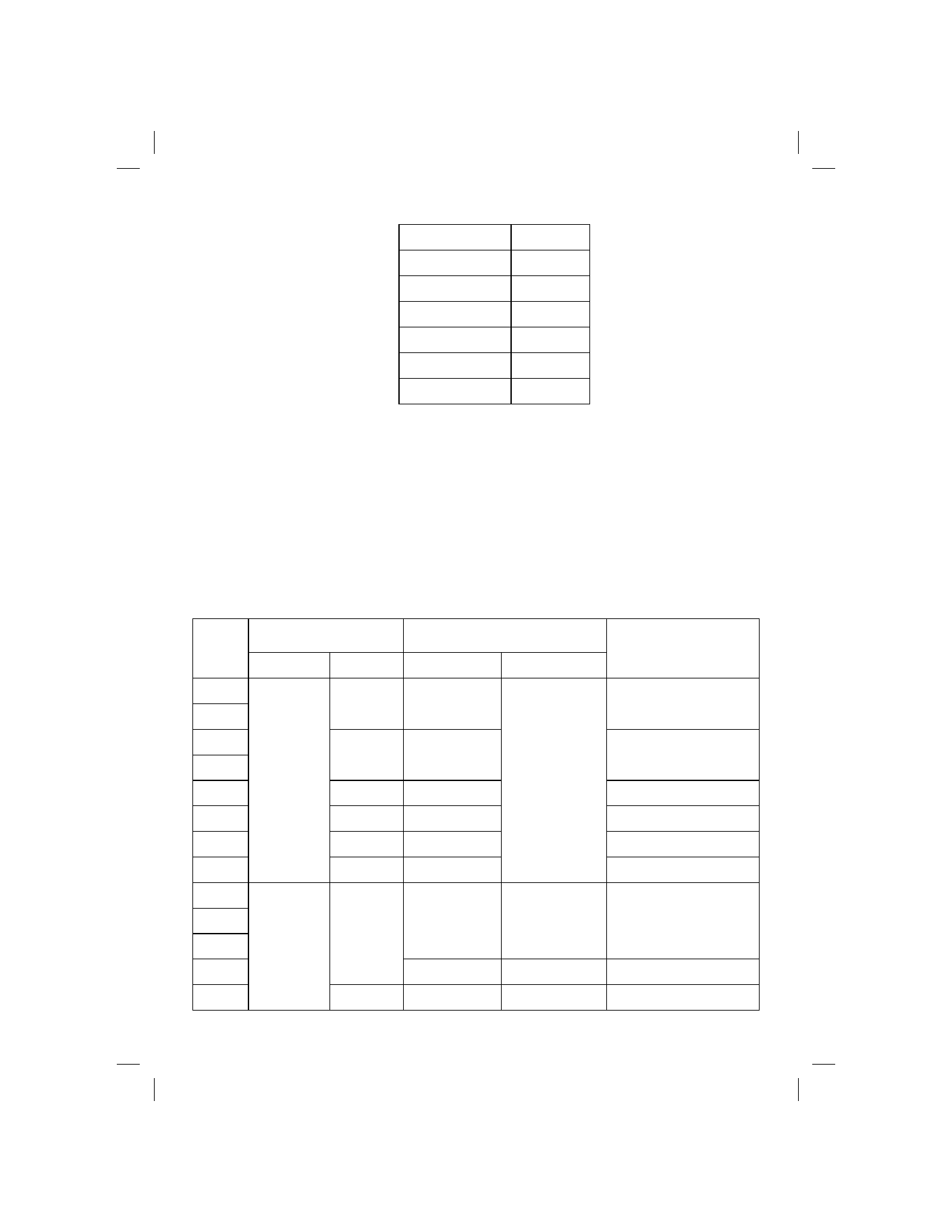
Table 4. Display Test
SELECT RANGE
DISPLAY
200
Ω
00.00*
2k
Ω
.0000*
20k
Ω
0.000
200k
Ω
00.00
2000k
Ω
000.0
20M
Ω
0.000
*The least significant digit(s) may change by several digits from zero, depending on your test lead resistance.
Linear Voltage Test
Use the following procedure to verify the proper operation of both the AC and DC V functions:
1.
Select DC V, 200mV range.
2.
Connect the calibrator HI volts output to the V-
Ω terminal and the calibrator LO volts output to the
COM terminal.
3.
For each step of Table 5, set the ACV/DCV switch to the indicated position, select the listed range,
program the calibrator for the corresponding input to the UUT, and verify that the UUT display value
lies within the indicated limits.
Table 5. Linear Voltage Test
UUT SWITCH POSITIONS
UUT INPUT
STEP
FUNCTION RANGE
LEVEL
FREQUENCY
DISPLAY READING
1
2
200mV
+190mVDC
-190mVDC
+189.90 to +190.10
-189.90 to -190.10
3
4
2V
+1.9VDC
-1.9VDC
+18990 to +1.9010
-1.8990 to -1.9010
5
20V
+19VDC
+18.990 to +19.010
6
200V
+190V DC
+189.90 to +190.10
7
1200V
+1000VDC
+999.3 to +1000.7
8
DCV
2V
Short
<.0020
9
10
11
190mVAC rms
100 Hz
10kHz
50kHz
188.90 to 191.10
188.90 to 191.10
180.20 to 199.80
12
200mV
100mVAC rms
1kHz
99.35 to 100.65
13
AC V
2V
1.9VAC rms
100Hz
1.8890 to 1.9110