Amprobe BDM40-UA Bench-Digital-Multimeter User Manual
Page 9
8
MEASUREMENT TECHNIQUES
The information provided here describes techniques in measurement and interpretation of measurements that
may extend the usefulness of your DMM. These techniques, common throughout the electronics industry, have
been tailored specifically for this instrument.
AC Measurement Techniques
When making precise measurements of AC signals, there are special parameters that must be considered such as
the type of AC converter the meter uses (average, rms, etc.), crest factor, bandwidth, noise, etc.
True RMS
In order to compare dissimilar waveforms, calculate Ohm's law statements or power relationships, you must
know the effective value of a signal. If it is a DC signal, the effective value equals the DC level. If the signal is AC,
however, we have to use the root mean square or rms value. The rms value of an AC current or AC voltage is
defined as being numerically equal to the DC current or voltage that produces the same heating effect in a given
resistance that the ac current or voltage produces.
In the past, average responding converters were the type of converter most widely used. Theoretically, the rms
value of a pure sine wave is
2
/
1
of the peak value and the average value is 2 / pi of the peak value. Since the
meters converted to the average value, the rms value was
pi
/
2
2
/
1
÷
=
)
2
(2
/
pi
= 1.11 of the average
value when measuring a sine wave. Most meters used an average responding converter and multiplied by 1.11 to
present true rms measurements of sine waves. As the signal being measured deviated from a pure sine wave, the
errors in measurement rose sharply. Signals such as square waves, mixed frequencies, white noise, modulated
signals, etc., could not be accurately measured. Rough correction factors could be calculated for ideal waveforms
if the signal being measured was distortion free, noise-free, and a standard waveform. The true rms converter in
your meter provides direct, accurate measurement of these and other signals. Since this DMM is AC and DC
coupled, refer to the section on Voltage Measurement Techniques for combined AC and DC signal measurements.
Crest Factor
Crest factor range is one of the parameters used to describe the dynamic range of a voltmeter's amplifiers. The
crest factor of a waveform is the ratio of the peak to the rms voltage. In waveforms where the positive and
negative half cycles have different peak voltages, the higher voltage is used in computing crest factor. Crest
factors start at 1.0 for a square wave (peak voltage equals rms voltage).
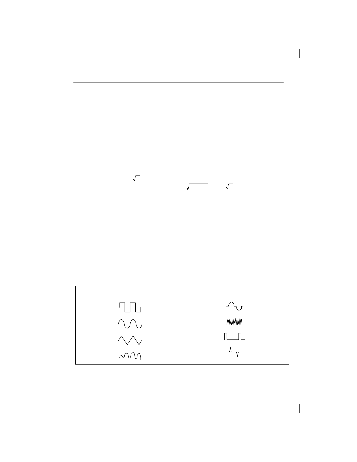
Figure 2 Crest Factors
CREST FACTOR
WAVE FORM
SQUARE
WAVE
SINE WAVE
TRIANGLE
SAWTOOTH
MIXED
FREQENCIES
SCR OUTPUT
WHITE NOISE
AC COUPLED
PULSE TRAIN
SPIKE
1.0
1.414
1.732
1.414 to 2.0
1.414 to 3.0
3.0 to 4.0
3.0
> 9.0
CREST FACTOR
WAVE FORM