Installation, 1 hardware description, 1 switch front panel – PLANET FGSD-1022 User Manual
Page 18
User’s Manual of FGSD-1022 Series
2. INSTALLATION
This section describes the hardware features and installation of the Managed Switch on the desktop or rack mount. For
easier management and control of the Managed Switch, familiarize yourself with its display indicators, and ports. Front
panel illustrations in this chapter display the unit LED indicators. Before connecting any network device to the Managed
Switch, please read this chapter completely.
2.1 Hardware Description
2.1.1 Switch Front Panel
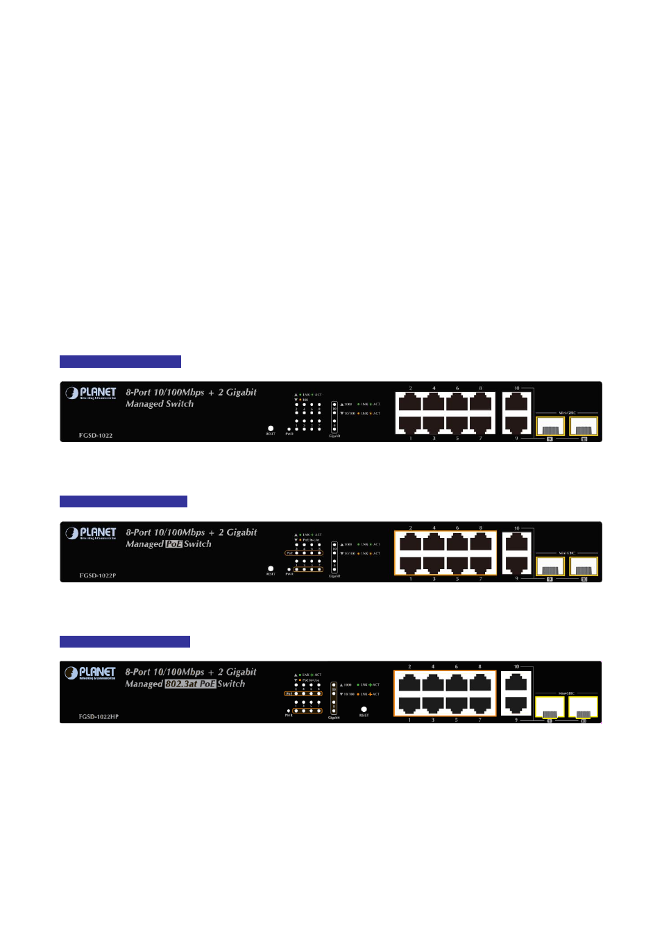
The unit front panel provides a simple interface monitoring the switch.
Figure 2-1 to 2-3
shows the front panel of the
Managed Switches.
FGSD-1022 Front Panel
Figure 2-1:
FGSD-1022 front panel
FGSD-1022P Front Panel
Figure 2-2:
FGSD-1022P Switch front panel
FGSD-1022HP Front Panel
Figure 2-3:
FGSD-1022HP Switch front panel
■ 10/100Mbps TP Interface (FGSD-1022, FGSD-1022P and FGSD-1022HP)
Port-1~Port-8: 10/100Base-TX Copper, RJ-45 Twist-Pair: Up to 100 meters.
18
■ Gigabit TP Interface
Port-9, Port-10: 10/100/1000Base-T Copper, RJ-45 Twist-Pair: Up to 100 meters.