Altera Stratix IV E FPGA User Manual
Page 19
Chapter 4: Development Board Setup
4–3
Factory Default Switch Settings
June 2011
Altera Corporation
Stratix IV E FPGA Development Kit User Guide
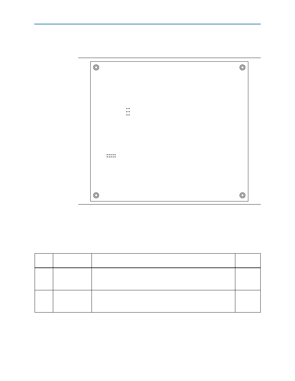
shows the switch locations and the default position of each switch on the
bottom side of the board.
To restore the switches to their factory default settings, perform the following steps:
1. Set the PGM CONFIG SELECT rotary switch (SW5) to the 0 position, as shown in
2. Set DIP switch bank (SW1) to match
Figure 4–2. Switch Locations and Default Settings on the Board Bottom
RLD_ZQ_IMPED
60
50
MAX
J28
DDR3_TEST_HDR
J29
Table 4–1. SW1 Dip Switch Settings (Part 1 of 2)
Switch
Board
Label
Function
Default
Position
1
CLK50_EN
Switch 1 has the following options:
■
When on, the 50 MHz clock is disabled.
■
When off, the 50 MHz clock is enabled.
Off
2
CLK66_EN
Switch 2 has the following options:
■
When on, the 66 MHz clock is disabled.
■
When off, the 66 MHz clock is enabled.
Off