Board-specific leds, Status and channel activity leds – Altera Arria GX Development Board User Manual
Page 30
2–20
Reference Manual
Altera Corporation
Arria GX Development Board
October 2007
General User Interfaces
Board-Specific LEDs
This section describes the board-specific LEDs. In addition to the
user-defined LEDs, the board provides a set of 4 yellow LEDs (2 per
interface). These board-specified LEDs display FPGA transceiver channel
activity (or traffic) for both TX and RX signals.
Table 2–17
shows the channels needing TX and RX LEDs.
Status and Channel Activity LEDs
The board provides status and channel activity LEDs, which indicate
successful configuration, power-on status, connection to the HSMC
expansion connector, etc.
Tables 2–18
lists the board status LEDs.
CLK_SEL0
Local oscillator / SMA input select (on = local oscillator)
C7
MAX_EN
Enables the PFL
F2
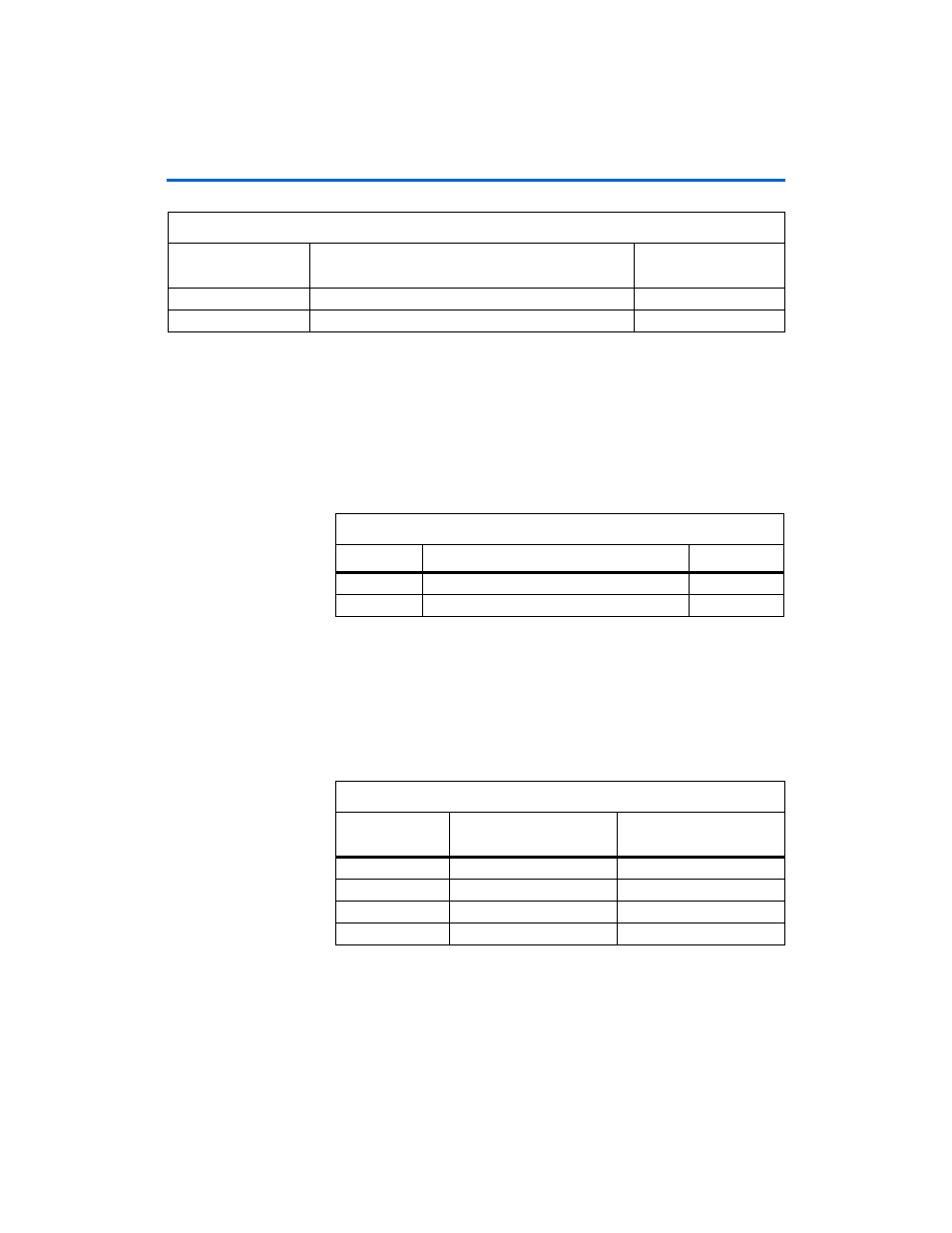
Table 2–16. Configuration DIP Switch Signal Name, Description, MAX II Device Pin Number (Part 2 of 2)
Schematic
Signal Name
Description
MAX II Device
Pin Number
Table 2–17. FPGA Transceiver Interface LEDs
Number
Transceiver Interface Indicator
LED Color
1
PCIe edge connector (
L0x1
,
L0x4
)
Yellow
2
HSMC interface (TX & RX)
Yellow
Table 2–18. Board Status LEDs
Board Reference
Number
Transceiver Interface
Indicators
Color
D1
HSMC present
Green
D2
CONF_DONE
Green
D11
POWER_ON
Blue
D21, D22, D23
Power_Good
Green