Expansion prototype connectors (proto1 & proto2) – Altera Nios Development Board Stratix II Edition User Manual
Page 26
2–16
Reference Manual
Altera Corporation
Nios Development Board Stratix II Edition
May 2007
Board Components
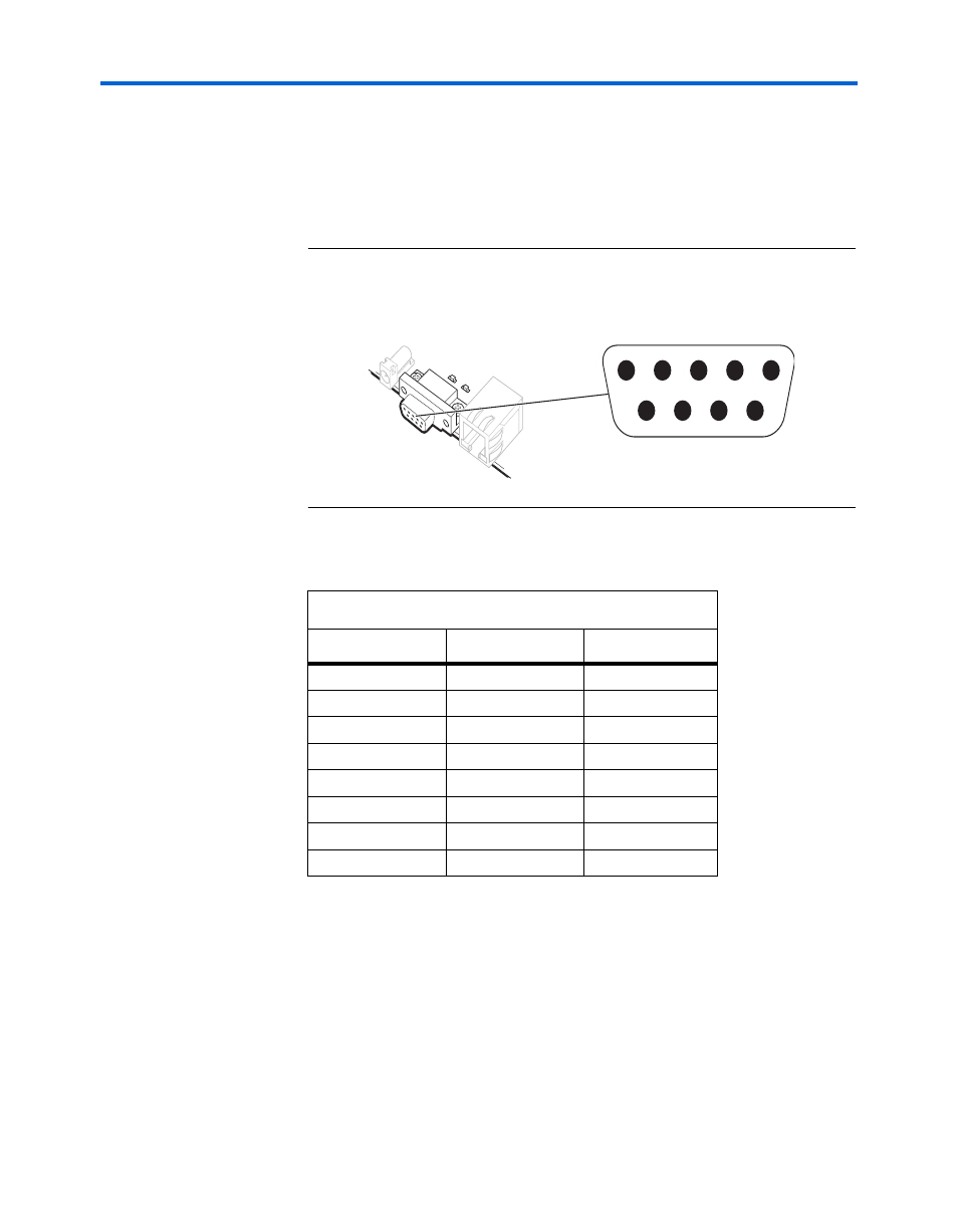
J19 is able to transmit all RS-232 signals. Alternately, the FPGA design can
use only the signals it needs, such as J19’s RXD and TXD pins. LEDs are
connected to the RXD and TXD signals and visually indicate when data
is being transmitted or received.
Figure 6
and
show the pin
connections between the serial connectors and the FPGA.
Figure 2–5. Serial Connector J19
Expansion
Prototype
Connectors
(PROTO1 &
PROTO2)
PROTO1 and PROTO2 are standard-footprint, mechanically-stable
connectors that can be used (for example) as an interface to a special-
function daughter card. Headers J11, J12, and J13
collectively form
PROTO1, and J15, J16 and J17 collectively form PROTO2.
The expansion prototype connector interface includes:
Table 2–10. Serial Connector Pin Table
FPGA Pin
J19 Pin
Board Net Name
AD26
3
serial_rxd
AB23
2
serial_txd
AC25
4
serial_dtr
AC24
1
serial_dcd
AB24
6
serial_dsr
K23
9
serial_ri
AB26
8
serial_cts
AD25
7
serial_rts
Function
Direction
Connector Pin #
Connector Pin #
Direction
Function
GND
5
DTR
IN
4
RXD
IN
3
TXD
OUT
2
DCD
OUT
1
9
OUT
RI
8
OUT
CTS
7
IN
RTS
6
OUT
DSR
J19