CIRCUTOR AR5L Series User Manual
Page 29
29
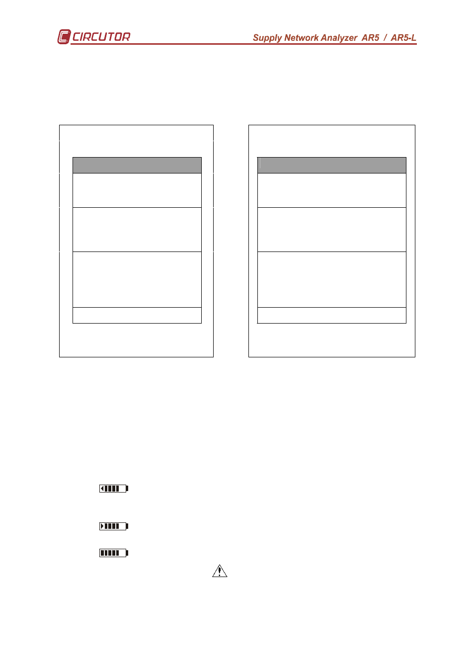
5.2.4.- Setup visualization
This screen permits to check all Setup parameters in the analyzer.
The screen on the left is the one shown on the analyzer’s display. The screen
on the right explains the meaning of each term.
HARMONICS
HARMONICS
SETUP
SETUP
Measure: 3Ф wire
1/1V
1000A - I
N
=100A
Type of measuring circuit
V.T. ratio
C.T. ratio/Neutral C.T.
File: Std-prog.STD
00:15:00 Harm. 50
Cyclical
RT xd :xxh :xxm :xxs
Name and type of file
Recor ding perio d Harmon ics
Memory type
Time of register
Trigger: Auto
0 0
00/00/92 00:00:00
00/00/92 00:00:00
Trigger parameter
Max. Value Min.
Value
Trigger: date On
Trigger: date Off
Com: 9600/ NO /8/1
Communication parameters
25/10/03 7:31:29
Preset date
5.3.- Warning messages
Some warning messages can appear at the visualization screens. These
messages inform about the ANALYZER performance:
-
STOP: The analyzer is not recording data.
-
RECORD: The analyzer is recording data.
-
TRIG?: Trigger conditions are not met. No data is being recorded.
-
M. Full: Memory is full.
-
M.Error: There is an error in the memory. The memory must be formatted.
-
Analyzer battery charge status. When only the symbol
3
3
3
3is shown,
it means that the battery is very low and the analyzer might turn off at any
moment.
-
The battery is charging. The user can also see the accumulated
battery charge level.
-
Full battery charge.
- WARNING MAX 500 V
: The maximum allowable phase to neutral
voltage of 500 V has been exceeded during the measuring process. When
measuring phase-to-phase voltages the limit is set at 866 V.