Maintenance, Wiring diagram, Agp pellet wiring diagram – Avalon Firestyles AGP User Manual
Page 43
Advertising
Maintenance
43
© Travis Industries
4141230
100-01270
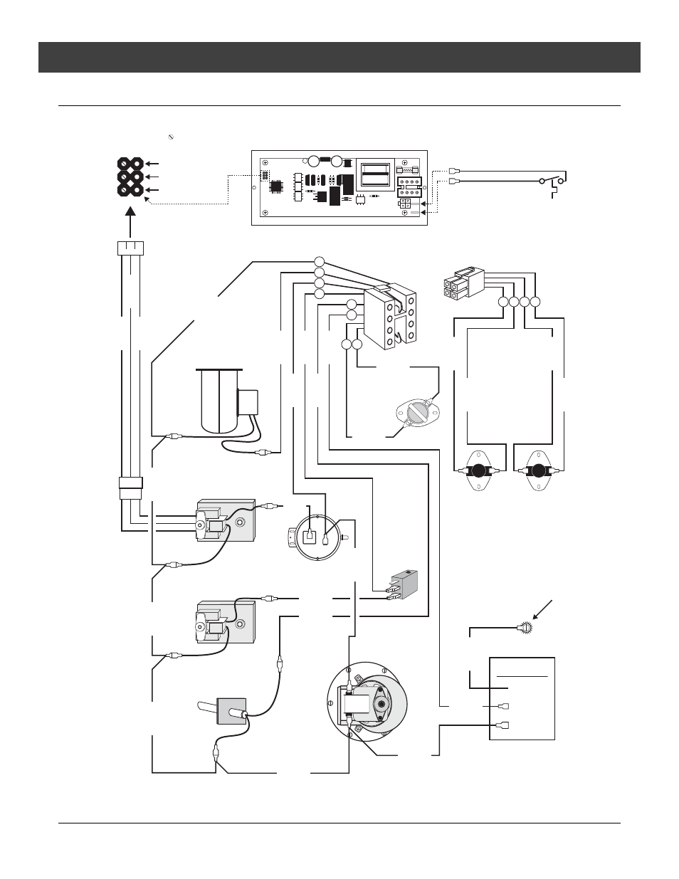
Wiring Diagram
AGP PELLET WIRING DIAGRAM
6 - Pin
Connector
Red Wire
White Wire
Black Wire
Uncovered
Pins
7
5
4
6
1
3
2 8
1
3
5
7
2
4
6
8
1 3 2 4
1
3
2
4
Optional Remote
or Thermostat
Power Cord
Ground
Hot (fuse)
Common
Black
White
Red
White
White
White
White
White
White
Brown
Black
Red
Black
Black
Brown
Brown
Black
Black
Red
Black
Black
Green
Orange
Orange
Gray
Gray
Control Board
Encoder Molex
Convection
Blower
Push
Auger Motor
Metering
Auger Motor
Igniter
Flow Switch
Exhaust
Blower
Ceramic
System Disc
120° NO
Hopper Lid
Switch
Hopper
Snap Disc
200° NC
Safety
Snap Disc
200° NC
Appliance
Ground
1004
Advertising