Integrating reset, Instantaneous overcurrent (50) element, 1 ampere unit pickup – Basler Electric BE1-50/51M User Manual
Page 16: 5 ampere unit pickup, Instantaneous overcurrent (50) element -6, Figure 1-3. integrating reset characteristic curve
1-6
BE1-50/51M General Information
9252000990 Rev R
Reset begins when the current drops below 95% of pickup and the relay has not timed out. Switch SW3-4
provides selection of either an instantaneous or integrating reset characteristic. Opening SW3-4 forces
the instantaneous reset timer to zero when timed dropout occurs. This fast reset characteristic prevents
the ratcheting effect that may occur with repeating system faults. Closing SW3-4 selects the integrating
reset characteristic. The integrating reset characteristic simulates the disk reset of electromechanical
relays. When the integrating reset characteristic is selected on 100 series relays, insure that sufficient
input power is available to power up the relay. This is not required on Series 200 relays. Series 200 relays
provide the integrating reset function even when input current falls to zero.
Integrating Reset
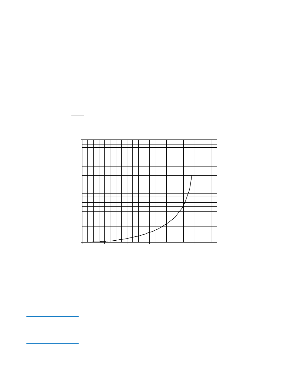
Integrating reset characteristics are defined by the following equation and shown in Figure 1-3. Equation
constants are provided in Tables 1-3 or 1-4.
Integrating Reset Equation:
1
−
=
2
R
M
RD
T
Where:
T
R
= Time to reset in seconds
R = Constant for the particular curve
D = TIME DIAL setting
M = Current in multiples of PICKUP setting during reset
Figure 1-3. Integrating Reset Characteristic Curve
Instantaneous Overcurrent (50) Element
Setting the INST PICKUP to the minimum pickup (0.2 on the 1 ampere unit and 1.0 on the 5 ampere unit),
places the relay in the most sensitive state and may be used as a safety setting.
Setting Range ............................ 0.2 to 19.8 Aac
1 Ampere Unit Pickup
Setting Increment ....................... 0.2 Aac
Accuracy .................................... ±2%, ±5 milliamperes at or above 0.2 ampere setting
Setting Range ............................ 1 to 99 Aac
5 Ampere Unit Pickup
Setting Increment ....................... 1 Aac
Accuracy .................................... ±2%, ±25 milliamperes at or above 1.0 ampere setting
1.0
10.0
100.0
0.000
0.200
0.400
0.600
0.800
1.000
1.200
Multiple of Pickup
xR
D
(S
ec
on
ds
)
P0
04
6-
11
Vertical axis xRD (Seconds) is applicable for all curves and is derived from
multiplying the constant R for the curve selected times D (the Time Dial setting).