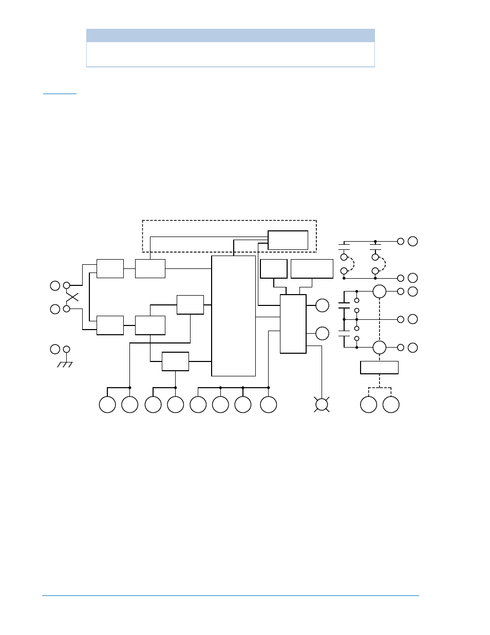
Auxiliary, Figure 3-1. functional block diagram – Basler Electric BE1-50/51M User Manual
Page 30
3-2
BE1-50/51M Functional Description
9252000990 Rev R
CAUTION
Trip circuit voltage is present at the front panel test points. When shorting the
test points, use insulated jumpers to avoid contact with these voltages.
The auxiliary output contacts can be configured by the user to close when the timed and/or instantaneous
trip occurs. With both jumpers installed (this is the factory setting) either the timed or instantaneous trip
closes the auxiliary contacts. Effective with unit revision R, in units 9252000100 through 9252000109, the
printed circuit board was changed. Now, the PCB for 100 and 200 series relays are similar. Users with
units before revision R may see Section 6, Relay Differences, for installing auxiliary output contact
jumpers.
Auxiliary
Figure 3-1. Functional Block Diagram
POWER
CT
SUPPLY
POWER
BRIDGE
CT
SIGNAL
TIME
SCALE
INST
SCALE
MUX
SW
SW
SW
SW
TIME
PICKUP
INST
PICKUP
SW
SW
SW
DOG
WATCH
SUPERVISOR
MICRO
51
50
TIME
DIAL
TIME
CURVE
50/60 Hz
INST DELAY
TP
TP
AUX
ISOLATION
TARGETS
MAGNETIC
ACTIVE/PICKUP
51
50
INPUT
GND
D1181-09
2
3
6
5
4
7
8
9
AND
A/D
CONVERTER
POWER-OFF
SENSING
SERIES 200 RELAYS ONLY
SW
RESET CHAR.
51
50