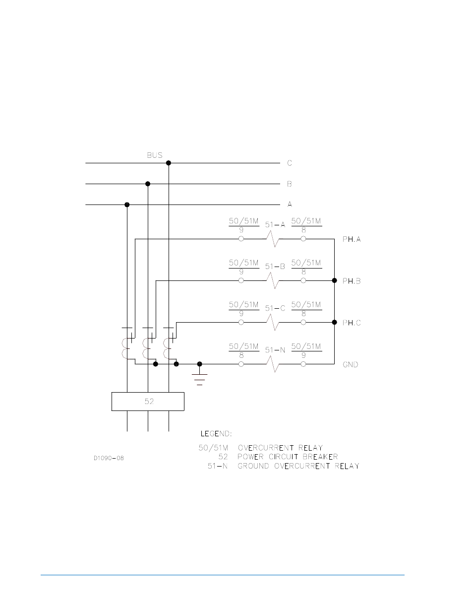
Figure 4-4. ac input connections – Basler Electric BE1-50/51M User Manual
Page 36
Advertising
4-4
BE1-50/51M Installation
9252000990 Rev R
Connections should be made with minimum wire size of 14 AWG except as noted for the ground wire.
Typical ac input and dc control connections are shown in Figures 4-4 and 4-5. The auxiliary output jumper
configuration schematic diagram is also shown in Figure 4-5. Relay internal connections are shown on the
back of the relay. Figure 4-6 shows a rear view of the relay and the connections.
Figure 4-4. AC Input Connections
Advertising