Shunt reactor protection application, Shunt reactor protection application -4, Three phase 87b relay – Basler Electric BE1-87B User Manual
Page 22: N1 2 3
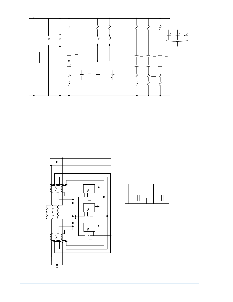
Figure 2-2. External DC Connections for Bus Protection
Shunt Reactor Protection Application
Differential protection of shunt reactors may be provided by using only one single-phase BE1-87B relay,
three single-phase relays, or one three-phase relay. Typical ac external connection diagrams for these
schemes are shown in Figures 2-3 and 2-4. The dc connections will be similar to those shown in Figure 2-
2. Only ground fault protection will be provided when one relay is applied. Application of either three-
phase arrangement will provide both multi-phase and phase-to-ground fault protection. Calculation of the
voltage tap setting is basically the same as for the bus application. The procedures for calculating the
voltage tap setting for either scheme are provided under Calculation of Settings.
Figure 2-3. External AC Connections for Shunt Reactor Protection,
Multi-Phase and Line-to-Ground Faults
86
86
86
BLOCK AUTOMATIC
RECLOSING
86
87
86
87
52-1
52-2
52-1
52-3
52-2
52-3
86
86
86
a
a
a
TC
TC
TC
(+)
(-)
D2853-4
5-24-99
87 - BE1-87B BUS DIFFERENTIAL RELAY
86 - LOCKOUT RELAY
15
16
17
18
TRIP 1
OUTPUT
TRIP 2
OUTPUT
19
20
87
13
14
VDIFF
ALARM
11
12
RELAY
TROUBLE
TO 2 AND 3
SINGLE PHASE RELAYS
TO 2 AND 3
SINGLE PHASE RELAYS
BE1 - 87B
86
BE1 - 87B
86
BE1 - 87B
86
1
2
3
01
02
03
86 - LOCKOUT RELAY
* TO SURGE GROUND
*
*
*
1
2
3
D2853-5
5-25-99
5
6
7
5
6
7
5
6
7
86
86
86
Three Phase
87B Relay
1
2
3
4
5
6
7
N
1
2
3
*
2-4
BE1-87B Application
9282300990 Rev P