Calculation steps, Example calculation, Calculation steps -17 – Basler Electric BE1-87B User Manual
Page 35: Example calculation -17
•
Z PCT – parallel equivalent impedance of n CTs.
•
Z BUS – parallel equivalent of the relay input impedance (5k) with Z PCT.
•
Z TOTAL – Z BUS + Z PCT.
•
I HT – Test current value for a HEALTHY current circuit.
•
V R TEST –voltage drop across R TEST during a HEALTHY test.
•
V Z BUS – voltage drop across Z BUS during HEALTHY test.
•
% V ALARM – ratio of V Z BUS to V ALARM setting. As a rule of thumb, use a minimum ratio of
110% to insure enough voltage for guaranteed operation.
•
I UHT – test current value for an UNHEALTHY current circuit.
Calculation Steps
Perform the following calculations to determine the appropriate secondary test voltage for the user
specific application.
1. Determine the V DIFF setting.
2. Using the 10% Alarm Voltage setting, determine the alarm value (V DIFF X .1 = V Alarm).
3. Calculate V test by Multiplying V Alarm times 1.5 (accounts for test circuit V drop and provides
guaranteed operation of V Alarm for healthy CT circuit).
4. From the user specific CT saturation curves, find Ie corresponding to the test source voltage (30 or
60) for the connected ratio (full ratio is recommended for bus differential protection).
5. Calculate the CT impedance (CTZ) (don’t worry about the reactive component) V Test/Ie.
6. Calculate parallel CT impedance (PCTZ) by dividing CTZ by the number of breakers in the bus
application (assumes all CTs on the bus are the same ratio and accuracy class).
7. Solve for Z Bus (relay input Z in parallel with the PCTZ) -- (PCT Z) (5000)/(PCT Z) + (5000).
8. Calculate I Healthy Test Current, I HT, by dividing the Test Source voltage V Test, by (Zbus+100)
(value of external R Test resistor=100 ohms).
9. Solve for voltage drop across the 100-ohm resistor (R x I).
10. Solve for voltage drop across Z Bus.
11. Solve for % V ALARM, V Z Bus/V ALARM setting. As a rule of thumb, use a minimum ratio of 110%
to insure enough voltage for guaranteed operation.
12. Divide Test Source Voltage by 100 = I UHT.
13. Verify that the Pickup Current setting of the relay is above the I Test Unhealthy.
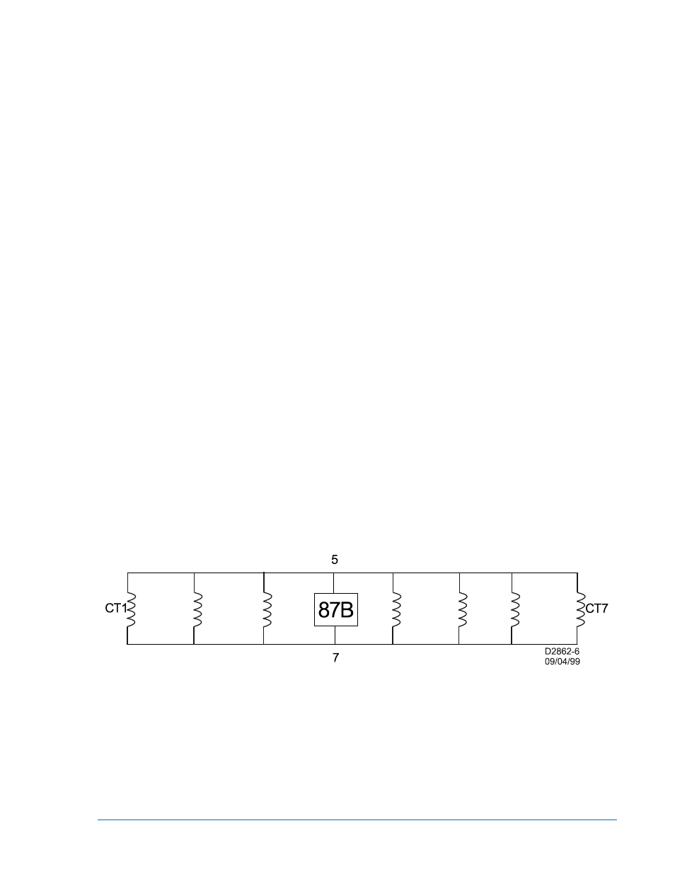
Figure 2-9. Voltage Appearing Across Full Winding of CT
Example Calculation
The following calculations are based on a seven-breaker bus as shown in Figure 2-9. For this example,
1200/5 CTs are used, all on the same ratio and same accuracy class as per Figure 2-6.
Based on a V Diff setting of 150 volts and an Alarm setting of 10 %, “V Alarm = (150) x .1 = 15 volts”. “V
Test = V Alarm X 1.5 or 15 X 1.5 = 22.5 volts”.
The user must select the 30 or 60-volt secondary taps based on the V Test calculation. If V Test is 30
volts or less, choose the 30-volt tap and if higher choose the 60-volt tap. In our example, V Test = 22.5
volts, therefore the 30 volt tap will be selected.
9282300990 Rev P
BE1-87B Application
2-17