Internal faults, Internal faults -7 – Basler Electric BE1-87B User Manual
Page 25
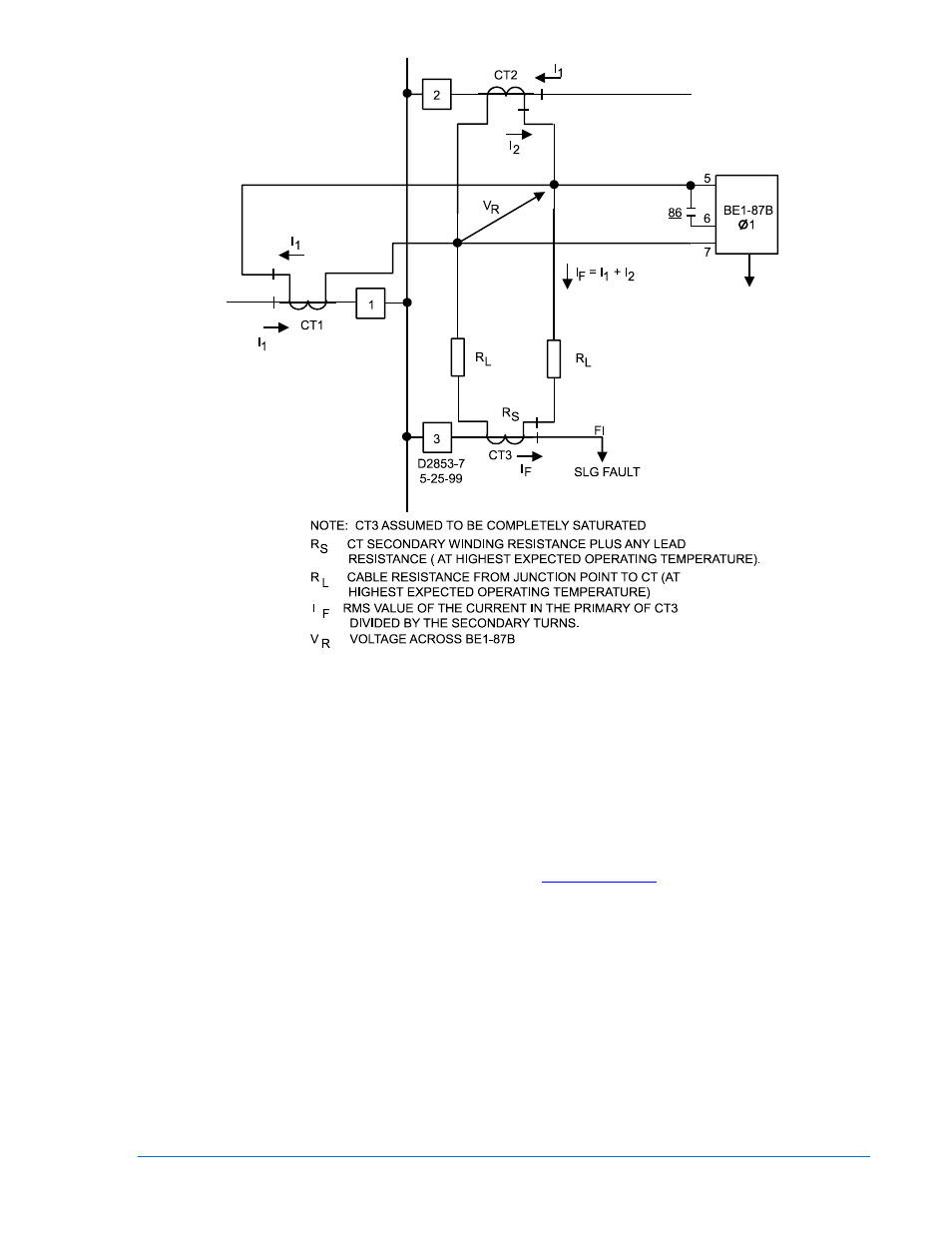
Figure 2-5. Illustration of Single Line-to-Ground Fault at Location F1
Internal Faults
During internal faults on the bus, all of the CTs will be operating into the relatively high impedance of the
BE1-87B. Under these conditions, the maximum fundamental frequency voltage that can be produced will
be limited to values as dictated by the CT secondary fundamental frequency excitation characteristics.
Examination of a typical CT secondary excitation characteristic will show that the available fundamental
frequency voltage flattens off beyond the knee of the curve. However, the peak voltages that can be
produced are not indicated on the standard excitation curve.
The concept of how the CT responds during an internal fault is given in greater detail in the paper “Bus
Protective Relaying, Methods and Application” located at
www.basler.com
. Let us summarize the matter
to say that, for internal faults, the peak voltages will always be greater than indicated by the average, and
will continue to increase in magnitude as the excitation is increased. Because the peak voltages during
internal faults will be much greater than the peak voltages experienced during external faults, and
because the BE1-87B relay operates as a function of the instantaneous voltage, the relay can be set to
be selective between internal and external faults. An indication of the peak voltages that a CT can
produce can be determined by a simple modification to the CT secondary excitation characteristic.
The modification is shown by the lines CPB in Figure 2-6, which now define the excitation characteristics
as a function of the peak voltages. Studies have shown that the peak voltages produced will be at least
equal to or greater than those established by the modified characteristics. These characteristics are
useful in determining the minimum internal fault for which the relay will operate. The method for making
the modifications, and their uses in determining the sensitivity, are provided in the Calculation of Settings,
Minimum Fault to Trip sub-section in this chapter.
9282300990 Rev P
BE1-87B Application
2-7