Alarm voltage test, Pickup voltage test, Alarm voltage test -4 – Basler Electric BE1-87B User Manual
Page 72: Pickup voltage test -4, Figure 5-3. alarm voltage test setup -4
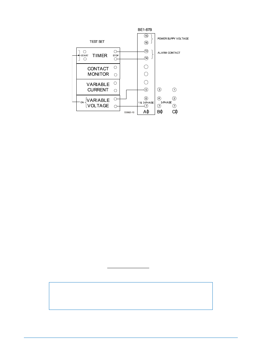
Alarm Voltage Test
Figure 5-3. Alarm Voltage Test Setup
1. Set the BE1-87B Pickup Voltage Control to 50 volts.
2. Set the Alarm Voltage Control to 10%. The Alarm Voltage pickup setting should be 5 volts rms (0.1 x
50)
±5%. Connect the relay as per the test diagram in Figure 5-3. Energize the relay power supply
and verify that the CT OV and Trip LEDs are reset.
3. Preset the Alarm Pickup Voltage to 90% of the pickup setting (4.5 volts rms). Set the timer to start on
application of test voltage and stop when the alarm contacts between terminals 13 and 14 close.
Apply the voltage to the relay for a minimum of 10 seconds and verify that the normally-open alarm
contacts between relay terminals 13 and 14 do not close (timer never stops) and the CT OV LED
does not light. Remove the test voltage.
4. Preset the Alarm Pickup Voltage to 110% of the pickup setting (5.5 volts rms). Set the timer to start
on application of test voltage and stop when the alarm contact between terminals 13 and 14 closes.
The alarm relay has intentional time delay to prevent nuisance alarms during normal operating
voltage excursions. Apply the voltage to the relay and verify that the alarm contact between relay
terminals 13 and 14 closes in several seconds and the CT OV LED lights. Remove the test voltage
and verify that the CT OV LED goes out.
5. With the Pickup Voltage Control set for 50 volts, repeat steps 2, 3, and 4 for the remaining Alarm
Voltage Control settings (20%, 30%, 40%, 50%, 60%, 70%, and 80% respectively). Repeat for B and
C phase test connections (three-phase model) and verify operation of the appropriate CT OV LED
(three-phase model).
Pickup Voltage Test
The pickup voltage test (Figure 5-4) verifies the rms firing point of the SCRs and seals through the
primary of T1 effectively shorting out the test source voltage. As a result, the following test should be
performed with a voltage source that will automatically turn off when the trip contact between terminals 17
and 18 closes.
NOTE
Select R
LOAD
that will cause the trip contacts to close (250 mA) or verify that the
voltage channel used for this test can supply 250 mA and cause the trip
contacts to close.
5-4
BE1-87B Testing
9282300990 Rev P