Ct test pushbutton, Circuit board controls, Intentional delay jumper – Basler Electric BE1-87B User Manual
Page 42: Ct test pushbutton -4, Circuit board controls -4, Intentional delay jumper -4, Figure 3-3. intentional delay jumper location -4
NOTE
The Trip Test pushbutton is functional only when operating power is applied to
the relay.
CT Test Pushbutton
This pushbutton control is used in conjunction with the optional Basler CT Diagnostic Test Source (P/N
9282300014) to verify the health of the CT input circuit. The condition of the CT input circuit is tested by
depressing the CT Test Pushbutton for one minute or until the CT OV LED lights. A healthy CT input
circuit is indicated by a lit CT OV LED and closed Alarm output contacts. A shorted CT input circuit is
indicated by the CT OV LED remaining off and the Alarm output contacts remaining open.
It may take up to one minute for the alarm to annunciate if the applied CT voltage is only slightly above
the alarm voltage. Applying a higher CT voltage will cause the alarm to annunciate sooner.
Details about CT input circuit testing are provided in the CT Test sub-section of Section 5, Testing.
Circuit Board Controls
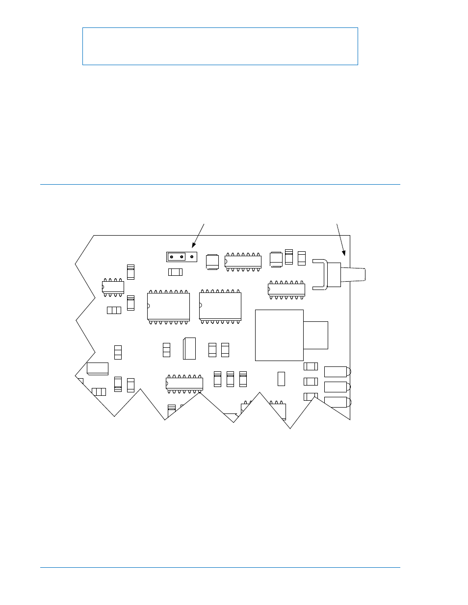
The BE1-87B relay has one circuit board control, the Intentional Delay Jumper. The jumper’s location is
illustrated in Figure 3-3 and its function is described in the following paragraphs.
Figure 3-3. Intentional Delay Jumper Location
Intentional Delay Jumper
A user-settable jumper is located on the Control circuit board and is used to select either no intentional
delay (jumper position 1 to 2), or a 20-millisecond delay
∗ (jumper position 2 to 3) added to the trip
response time. For applications having a tap within the zone of protection that is protected by a high-
speed fuse, the 20 millisecond intentional delay
∗ is intended to prevent tripping the bus for a fault on the
fused tap. The current detector circuit reset time is approximately 1 millisecond so that the ac and dc
components of the differential current, as reproduced at the CT secondary, must drop below pickup in
less than 19 milliseconds. A secondary error may occur due to the fast dropout of the primary current
when the fuse operates.
∗ Actual intentional time delay is a function of pickup current. For currents exceeding twice the pickup
setting, intentional time delay is 20 milliseconds. For currents less than twice the pickup setting,
intentional time delay is 25 milliseconds.
U1
1
UC1
AGND
SW2
SW1
W1
1
CRC1
CRC2
CRC6
CR1
CRC1
8
CRB18
CRA
1
8
AR1
C3
+
C2
+
U4
U1
C3
4
CC1
5
RC2
2
CC24
RC18
RA18
RB18
R7
R4
U5
U3
U2
DSB1
DSA1
DSC1
SW5
R24
R2
7
Intentional Delay Jumper
D2853-14
01-03-03
Reset Switch
2
3
CONTROL
CIRCUIT BOARD
3-4
BE1-87B Human-Machine Interface
9282300990 Rev P