Basler Electric BE1-87B User Manual
Page 27
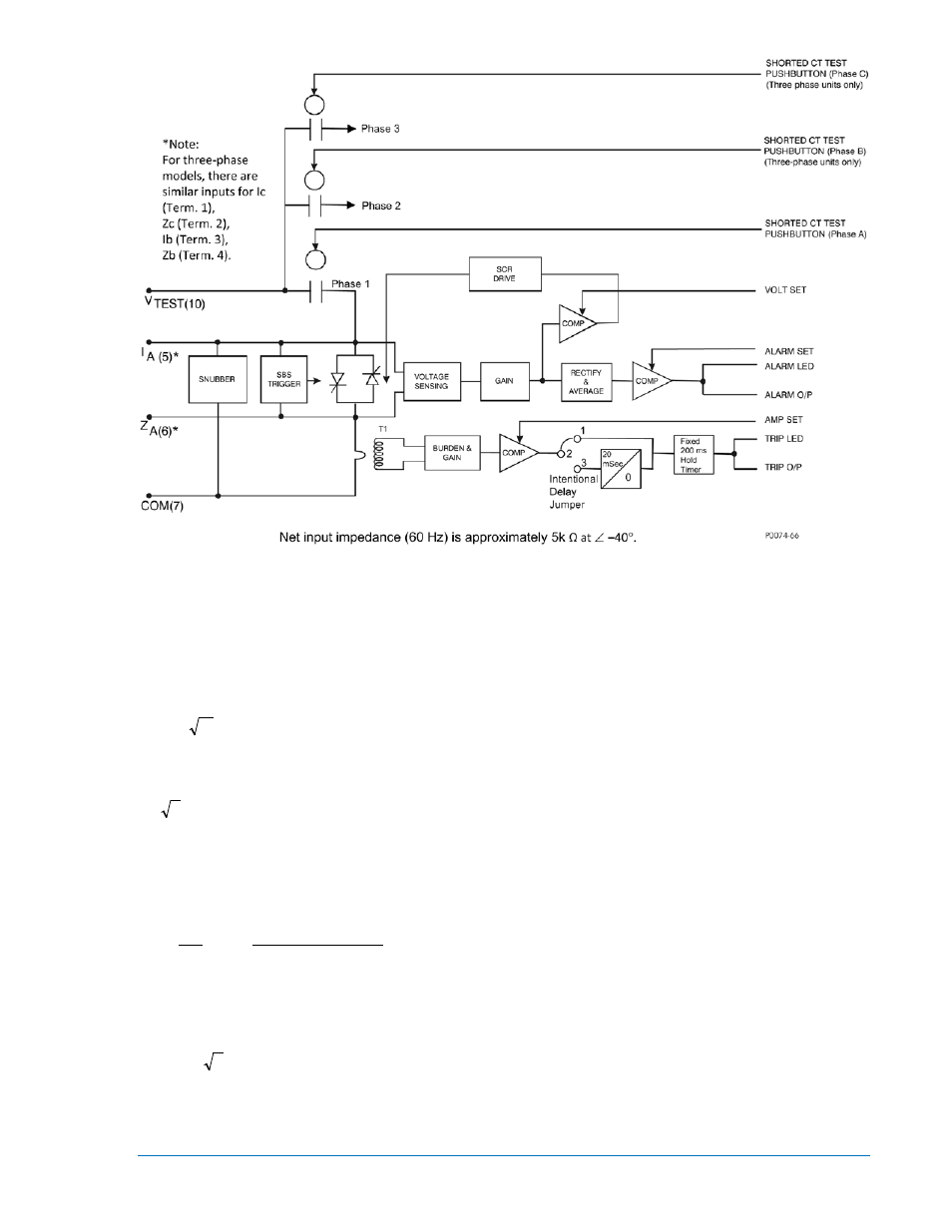
Figure 2-7. Simplified Internal Connection Diagram for BE1-87B Relay
For convenience, the BE1-87B relay voltage settings are calibrated in terms of rms symmetrical volts and
all calculations for settings are made in terms of rms symmetrical quantities. The relay responds to the
instantaneous value of applied voltage, and this maximum instantaneous value can be two times the
square root of two or 2.83 times V
DIFF
for fully offset waveforms. As soon as the relay operates, the
shorting action of the SCR path reduces this voltage to a very low level. Thus the maximum peak voltage
that can be produced in the differential circuit will be limited to the value calculated in Equation 3 below.
)
(V
(2.83)
)
(V
2
2
V
DIFF
DIFF
R
=
=
(EQUATION 3)
V
R
= maximum instantaneous peak voltage that can be developed in the differential circuit
V
DIFF
= BE1-87B voltage set point in rms symmetrical volts
(
2
2
) = conversion of rms symmetrical volts to corresponding peak volts of a fully offset voltage wave
Where CTs with taps set on other than the full winding are involved, the voltage developed across the full
winding of these CTs can be greater than the differential circuit voltage as a result of the autotransformer
action. For example, consider the simple circuit of Figure 2-8. The voltage in the differential circuit, and
consequently across CT1 and CT2, will be limited to V
R
. But the voltage across the full winding of CT3 will
be greater by the ratio of the total number of turns of the CT to the actual turns used.
2
1
DIFF
R
2
1
F
N
)
(N
)
(V
(2.83)
)
(V
N
N
V
=
=
(EQUATION 4)
V
F
= voltage across the full winding
N
1
= total number of CT secondary turns
N
2
= number of CT secondary turns used, i.e. tap settings
2.83 =
2
2
(peak value of fully offset wave)
The voltage across the full winding (V
F
) should not exceed the insulation breakdown of the connected
equipment. The value of the actual peak voltage that can be produced for any relay tap setting and mixed
multi-ratio CT combination may be evaluated using Equation (4).
9282300990 Rev P
BE1-87B Application
2-9