Pickup current test, Pickup current test -5, Figure 5-4. pickup voltage test setup -5 – Basler Electric BE1-87B User Manual
Page 73
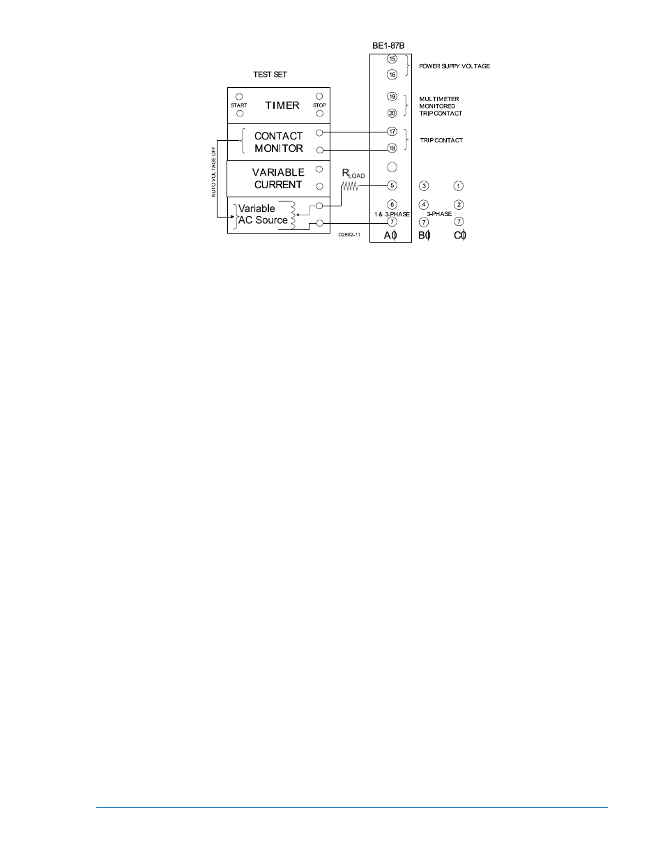
Figure 5-4. Pickup Voltage Test Setup
1. Set the 87B Pickup Voltage Control to 50 volts. Set the Pickup Current Control to 0.25 amperes. The
87B Test Pickup Voltage should be 100 volts rms symmetrical or twice the Pickup Voltage setting
(this is the rms test value equivalent to a fully offset waveform). The CT OV LED will light during this
test, as the Alarm Pickup Voltage will be exceeded. Connect the relay as per the test diagram in
Figure 5-4. Verify that the CT OV and Trip LEDs are reset.
2. Configure the test voltage source to automatically turn off when the trip contact closes. Preset the
Test Pickup Voltage to 95 volts rms. Apply the test voltage and note that the relay does not trip.
Slowly increase the test voltage until the trip output contacts close and the Trip LED lights (100 volts
±5%). Note that the Trip LED remains lighted after the test voltage has been removed. Press the
Reset pushbutton to turn off the Trip LED.
3. Set the Pickup Voltage Control to 100 volts and the Pickup Current Control to the 0.25 amperes. As
described above, the Test Pickup Voltage will be twice the selector switch voltage or 200 volts rms
symmetrical. The CT OV LED will light during this test, as the Alarm Pickup Voltage will be exceeded.
Connect the relay as per the test diagram in Figure 5-4. Verify that the CT OV and Trip LEDs are
reset.
4. Configure the test voltage source to automatically turn off when the trip contact closes. Preset the
Test Pickup Voltage to 190 volts rms. Apply the test voltage and note that the relay does not trip.
Slowly increase the test voltage until the trip output contacts close and the Trip LED lights (200 volts
±4%). Note that the Trip LED remains lighted after the test voltage has been removed. Press the
Reset pushbutton to turn OFF the Trip LED. Return the Pickup Voltage selector switch to the 50-volt
setting.
5. Repeat the 100 and 200 volt tests for B and C phases test connections (three-phase model) and
verify operation of the appropriate Trip LED (three-phase model).
6. The full Pickup Voltage range of the relay was tested previously under Pickup Voltage Control Test.
The 100 and 200 volt test points used under Pickup Voltage Test verify that the voltage sensing
circuit and the pickup voltage setting (scaling) circuit are working together and will fire and seal the
SCRs through T1. There is no need to apply higher rms test voltages to the relay.
This completes the voltage tests for the BE1-87B. Set the Alarm Voltage and Pickup Voltage Controls to
the values calculated for the user’s specific application.
Pickup Current Test
1. Connect the test circuit as shown in Figure 5-5.
2. Set the Pickup Current Control to the 0.25 amp position. Apply the current test source. Slowly
increase current until the output contacts close and the Trip LED lights.
3. Remove the current test source and verify that the Trip LED remains lighted. Pickup should be 0.25
amps
±5%. Press the Reset button to turn off the Trip LED.
9282300990 Rev P
BE1-87B Testing
5-5