Mixing two different ratio cts, General settings guidelines, Operating principles – Basler Electric BE1-87B User Manual
Page 23: Mixing two different ratio cts -5, General settings guidelines -5, Operating principles -5, Be1 - 87b
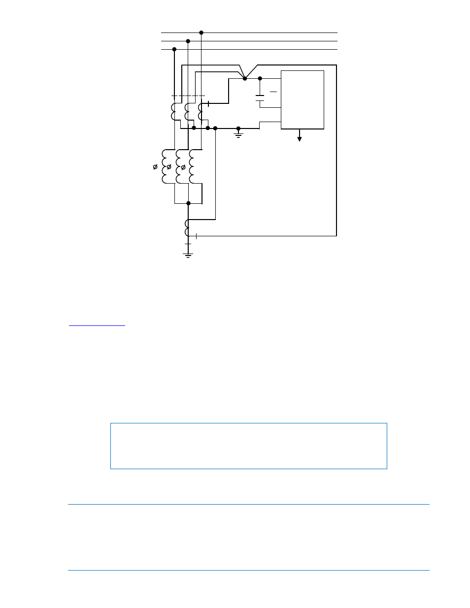
Figure 2-4. External AC Connections for Shunt Reactor Protection, Ground Faults
Mixing Two Different Ratio CTs
While high impedance bus protection is best configured with all CTs having a common ratio, it is possible
to utilize two different ratio CTs within one bus protection zone. The process by which this is
accomplished is detailed in the paper “Bus Protective Relaying, Methods and Application” located at
www.basler.com
.
General Settings Guidelines
To obtain the maximum setting sensitivity, the CT loop resistance should be minimized so that the lowest
possible voltage setting can be selected. For switchyard applications where there is a large distance
between the breaker and the relay panel, it may be desirable to locate the differential junction in the
switchyard since the resistance of the fault CT loop may otherwise be too large. To minimize the
impedance from the current transformers to the junction point, all the secondary windings should be
paralleled in the switchyard and as close as possible to the current transformers. Optimally, the junction
point should be equidistant from all current transformers.
NOTE
The cable resistance from the junction point to the relay is not included as a
part of the fault CT loop resistance. It is permissible to locate junction points at
the panel, providing that the relay setting gives the desired sensitivity.
Operating Principles
The BE1-87B high impedance, differential relay operates on the instantaneous value of CT secondary
voltage to which the relay is connected. All the CTs in the differential circuit must have the same turns
ratio. If all CTs have the same turns ratio, the voltage developed across the relay during normal system
conditions is very small. The diagram in Figure 2-1 illustrates typical external ac connections to the relay
for use in a bus differential scheme. As shown in the diagram, a typical differential connection is used
consisting of the CT circuits from each bus device connected in wye and paralleled at one location
BE1 - 87B
5
6
7
86
TO SURGE
GROUND
1
2
3
1
2
3
86 - LOCKOUT RELAY
D2853-6
5/25/99
9282300990 Rev P
BE1-87B Application
2-5