Basler Electric BE1-87B User Manual
Page 26
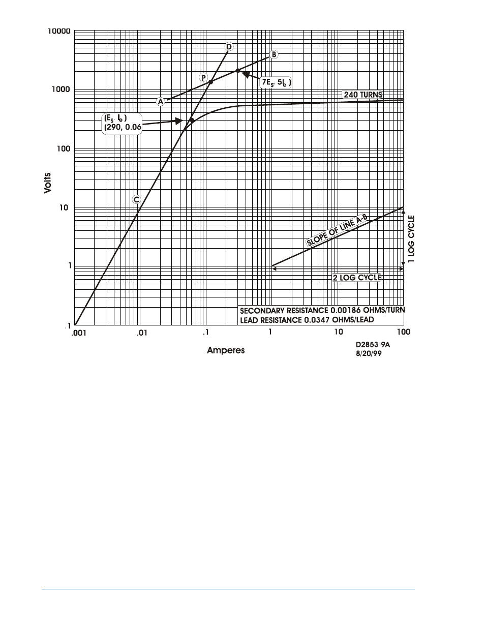
Figure 2-6. Typical Secondary Excitation for 1200/5 Bushing Current Transformer
Figure 2-7 illustrates, in simplified form, the internal connections of the BE1-87B relay. When an internal
fault occurs, the peak voltage developed in the secondary of the feeder CTs will appear across the relay
input network via phase A, phase B, or phase C. Under normal conditions, while operating power is
available to the relay, the SCR firing is accomplished via the voltage sensing circuitry by the pulse
amplifier. When the SCRs fire, the CT circuits will be shorted and the total secondary fault current will flow
through the SCR circuits and the primary of current transformer T1. If the total secondary fault current,
and hence the primary current of T1 is above the pickup level of the relay, a trip output will be provided
via the output relay.
When relay-operating power is not available, the BE1-87B can no longer trip the output contacts.
However the SBS (Silicon Bilateral Switch) circuitry provides voltage protection for the SCRs and the
relay internal circuitry. When the peak voltage exceeds the switching voltage of the SBS, it will conduct,
causing the corresponding SCR to be triggered to the ON condition. During subsequent half cycles, the
SCRs will be triggered alternately. Note that the SBS, across the SCRs, exhibits high impedance in the
OFF state and will turn ON and conduct when a switching voltage above the relay maximum setting is
reached. The SBS acts only as a failsafe, triggering the SCRs in the event control power (power supply
voltage) is lost and a fault has occurred.
2-8
BE1-87B Application
9282300990 Rev P