Architecture of the power supply units, General control block" (gcb) – BECKHOFF CX1100-000x User Manual
Page 10
Product overview
8
Embedded PC
interfaces.
Architecture
Display
Taster
Architecture of the power supply units
The four power supply units for the CX10x0-System accomplish more task than supporting the system with power.
Each module has three basic functions. Additional each model supports different connection to communication
busses. Caused by these different connections the internal architecture differ. At first the common functions are
described.
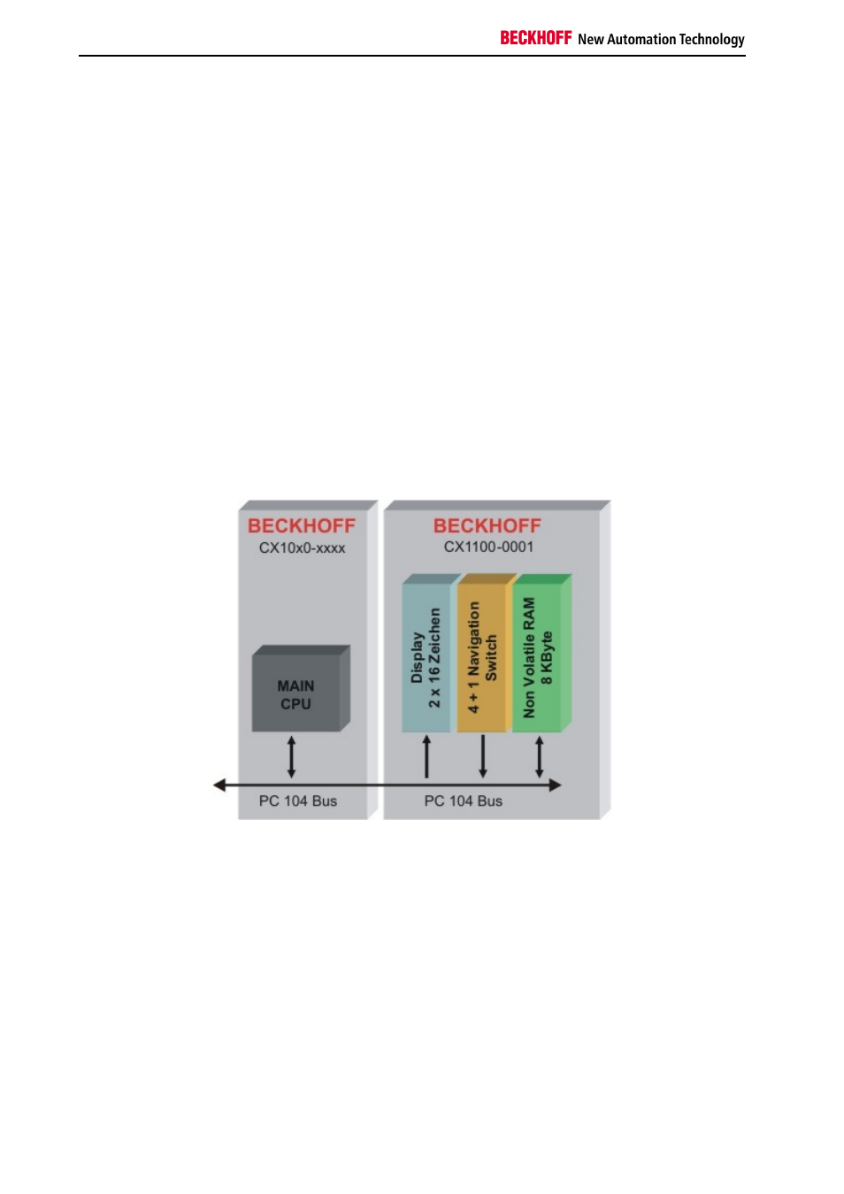
All power supply feature, except for power supply, the following functions:
1.
Display 2 x 16 characters
2.
4+1 navigation switch
3.
Non Volatile RAM
These functions are managed by the control program via the PC104 bus. The structure of the CX1100-0001 is shown
in the following figure:
"General Control Block" (GCB)
The top 16 byte of the system control area (starting at the physical hex address D0000 + Offset FF0) form the
general control block GCB, which holds the control byte required to start the I/O processing of the K-Bus and IP-Link.
The CPU of the main module controls the whole architecture. With memory mapped I/O regions data can be
exchanged. The data needed to run the system is combined in the "General Control Block" (GCB). Its base address
is "0xD1000". The figure shows the Data and the offset. Some registers are not needed in all units. So only the
requested registers are mapped other addresses are masked out.