BECKHOFF CX1100-000x User Manual
Page 22
Product overview
20
Embedded PC
4 + 1 navigation switch
Operating principle of the switch
The CX1100-000x power supply units all have 4 + 1 navigation switches. The switches can therefore be used to input
five basic states:
1.
UP
2.
DOWN
3.
LEFT
4.
RIGHT
5.
SELECT
Combined inputs, such as UP + RIGHT or UP + RIGHT + SELECT can also be entered. The values of the switches
are stored in a register of the "Auxiliary Control Block", ACB. Details may be referred to in the architectural
description.
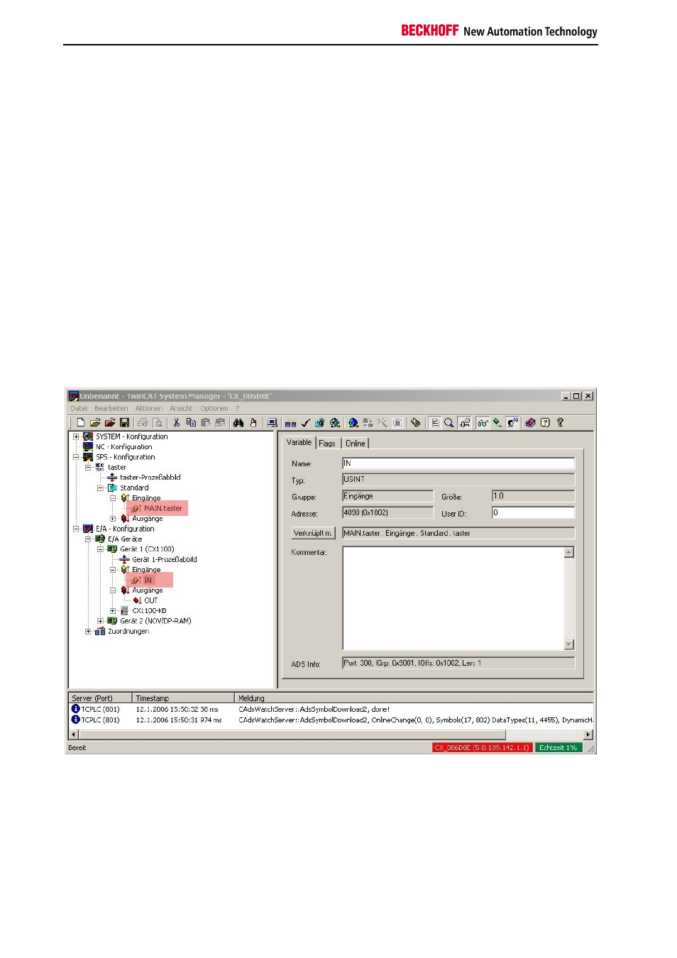
The register can be accessed from within a PLC program, and the value can be assessed. This requires a variable of
type USINT first to be created in the PLC program. This is then linked in the TwinCAT System Manager to the IN-
register of the CX1100.
The figure shows the linked signals (with a bright red background). The switch can be accessed from the PLC
program through the Switch variable. The PLC program takes the form described below. To begin an external
variable is declared as an input. (In this example it is at address 0)