BECKHOFF CX1100-000x User Manual
Page 31
Product overview
Embedded PC
29
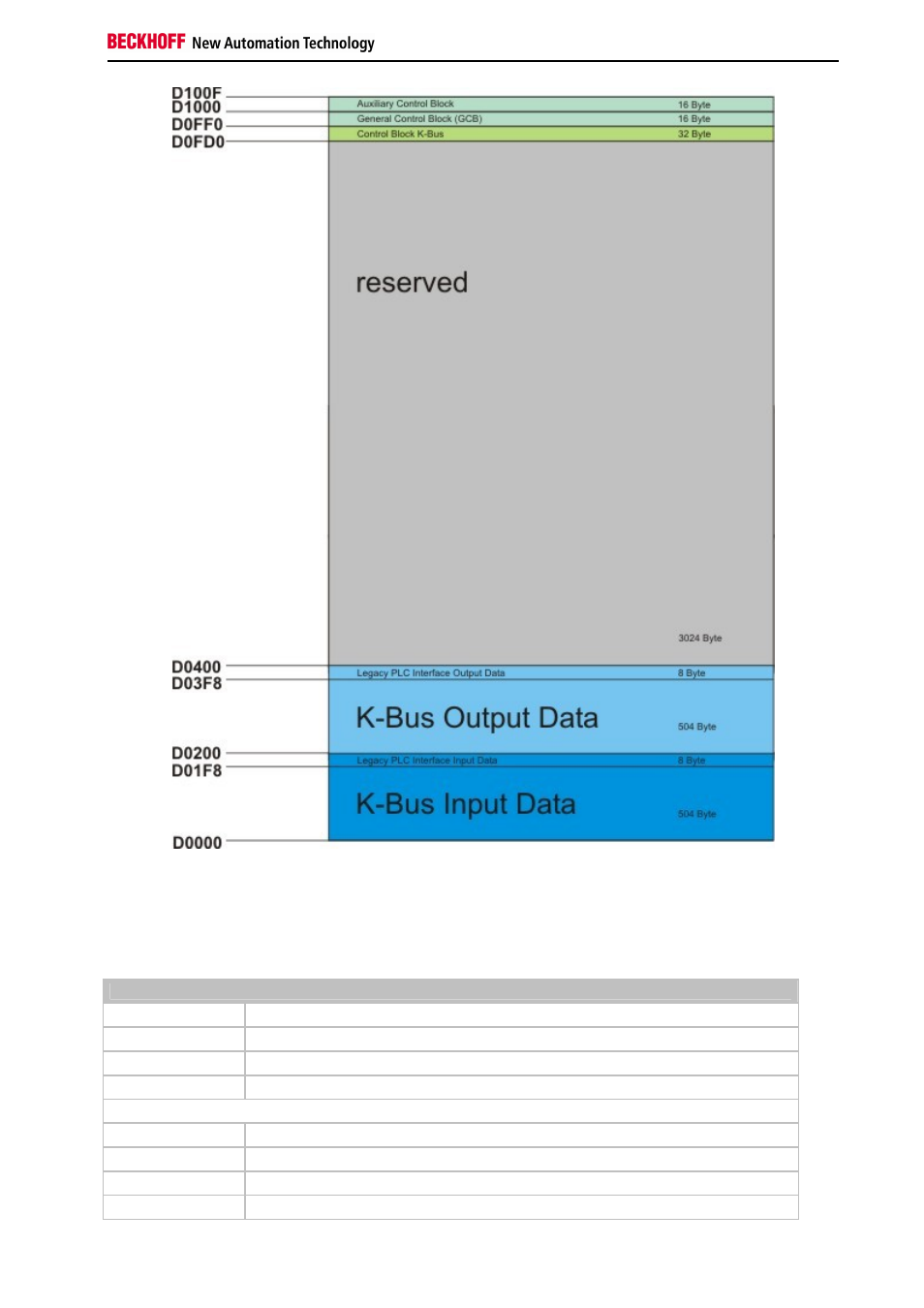
The memory image of the K-bus resides in the lower memory region (D000 to D0400). This region separates in input
and output region. Since firmware version ≥ B3 it is possible to shift the I/O regions. In this way the process image
can be adapted to the needed space. To each I/O-region the is a control block. Each block consists of 8 byte for
diagnosis purpose. These regions can be shifted, too. The following table shows the structure of the interface. The
offset addresses are default values.
Legacy PLC interface (inputs)
Offset
default
0x1F8 [2]
diagnosis CX1100-0002 to K-Bus
0x1FA [2]
2 Byte PLC Interface CX1100-0002 to K-Bus
0x1FC [4]
reserved
Legacy PLC interface (outputs)
Offset
default
0x3F8 [2]
diagnosis K-Bus to CX1100-0002
0x3FA [2]
2 Byte PLC Interface K-Bus to CX1100-0002
0x3FC [4]
reserved