BECKHOFF CX1100-000x User Manual
Page 14
Product overview
12
Embedded PC
Link) in order to read input values and write output values. The procedure is the same for IP-Link, the description
limits itself to K-Bus for textual simplicity.
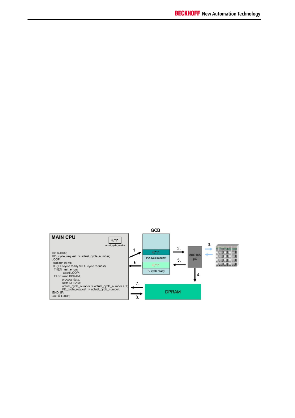
The I/O operation is done through the bytes named "PD cycle ready" and "PD cycle request" in the GCB. The K-Bus
cycle is triggered by a write operation to the byte "PD cycle request". Although the value being written to this byte
does not matter (it is only the write operation which is important), it is recommendable write a counter-up value to this
byte. The microcontroller for the K-Bus will react to the write operation by performing a K-Bus cycle and gathering the
I/O data. Once the cycle is completed and the electrical signal input data are written to the DP-RAM, the
microcontroller will set the content of byte "PD cycle ready" equal to the content of "PD cycle request", thus signaling
the completion of the I/O cycle. The time required to run a K-Bus cycle depends on the number of terminals attached
to CX1100: it is minimum 700 microseconds and typically well below 5 milliseconds. The K-Bus cycle time can be
viewed by using the TwinCAT System Manager tool, by entering the exact terminal configuration.
At startup of the user program, before going into cyclic operation, it is mandatory to reset the K-Bus controller by
triggering the "RES C165" bit in the Auxiliary Control Block section of CX1100. Please refer to the description of the
ACB for how to do this.
The sequence of operating the K-Bus can be explained by assuming a cyclic automation task executed each 10 ms
on the main CX1000 CPU:
Task cycle "n":
- check if K-Bus operation of previous cycle has finished: is "PD cycle ready" = "PD cycle request" ? Proceed if yes,
issue error message and abort cyclic task operation if not, because a K-Bus cycle does not need 10 milliseconds to
finish !
- read the input data from the DP-RAM (these are the input data gathered by the previous cycle "n-1" )
- write the output data to the DP-RAM (these are the outputs calculated by the previous cycle "n-1" ).
- increment and write the new value to "PD cycle request"
- perform task user code
Task cycle "n+1":
- check if K-Bus operation of previous cycle has finished: is "PD cycle ready" = "PD cycle request" ? Proceed if yes,
issue error message and abort cyclic task operation if not, because a K-Bus cycle does not need 10 milliseconds to
finish !
- read the input data from the DP-RAM (these are the input data gathered by the previous cycle "n" )
- write the output data to the DP-RAM (these are the outputs calculated by the previous cycle "n" ).
- increment and write the new value to "PD cycle request"
- perform task user code
Of course only the I/O bytes needed should be copied to or from the DP-RAM, since each read or write operation
over PC104 is time consuming. Please note that the terminal outputs need a K-Bus refresh no later than 100
milliseconds, otherwise the watchdog in each terminal will shut off the outputs. This means that the task cycle time
should be below 100 milliseconds. Also, if more than one cyclic automation task needs access to K-Bus I/O, it is
important that only one task operates the K-Bus and the other tasks implement an I/O buffering in order to have a
consistent I/O image. In this scenario, the task with the highest priority has the shortest cycle time and will trigger the
K-Bus.
Please note also that it is assumed that in each cycle the integrity of the K-Bus is being checked by examining the
"Processdata error" field in the GCB. Cyclic operation should be aborted in the case of an I/O error and user should
be prompted for corrective actions. Cyclic operation can be resumed after resetting the faulty bus over the service
request fields of the control block.