Auxiliary control block" (acb), Cycle time, Watchdog error counter – BECKHOFF CX1100-000x User Manual
Page 12: Processdata error, Processdata cycle overrun, Pd cycle ready / pd cycle request
Product overview
10
Embedded PC
Cycle Time:
This is the time elapsed between the initiation and termination of an I/O process image update (K-Bus + IP-Link ).
The time is recorded in units of microseconds and starts with writing a new cycle request to the field "PD cycle
request" and it stops with the termination response in the field "PD cycle ready". For CX1100-0002 this time reflects
the K-Bus update time, for CX1100-0003 it is the sum of K-Bus update time and IP-Link update time.
Watchdog Error Counter:
If the Watchdog Time exceeds the value in this register is increased by one. In this way the user can get the numbers
of watchdog-time errors. (available since firmware revision B6)
Processdata Error:
This byte contains the information on the error status of the I/O blocks. The possible bit codes are:
Bitfeld
Bit 7
Bit 6
Bit 5
Bit 4
Bit 3
Bit 2
Bit 1
Bit 0
Processdata Error
-
-
-
-
-
-
IP-Link Error
K-Bus Error
The bit is set to "TRUE", if an error occurred. If both bits are zero, there is no error on either bus system. Error
recovery may be attempted by invoking the "Reset bus" service in the corresponding CB of either K-Bus or IP-Link.
Processdata Cycle Overrun:
This byte contains a counter, which is incremented each time a new process data cycle is requested although the
previous cycle has not yet completed. This can happen only due to a handshake programming error or if the user
task cycle time is shorter than the time for I/O update.
PD Cycle Ready / PD Cycle Request:
These two bytes contain the request value and the ready value for operating a process data (PD) I/O cycle. The user
program is supposed to write a pattern (e.g. an up-counter value ) to the request byte, thus triggering the I/O cycle.
Once the I/O cycle is finished, the microcontroller will set the ready byte to match the request byte. A new request
can then be written to the request byte.
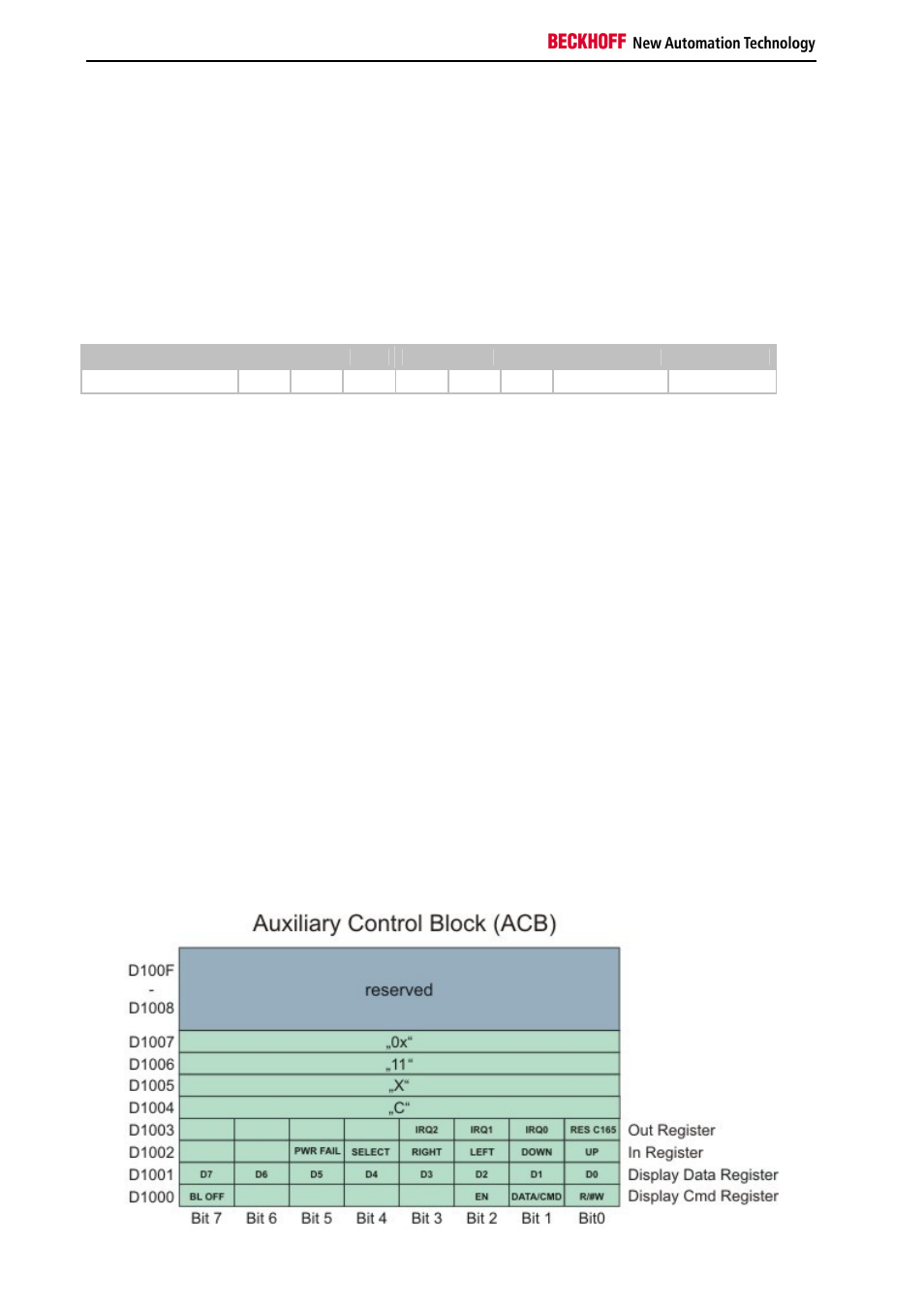
"Auxiliary Control Block" (ACB)
The Auxiliary Control Block of CX1100 is a block of 16 bytes and starts at address D1000 (hex). It is a miscellaneous
control block for controlling:
- the 2x16char FSTN LCD Display
- the navigation switch
- the hardware reset of the 80C165 microcontroller
The following schematic shows the layout of the ACB and is followed by a description of the single bits contained in it.