The k-bus control block (cb k-bus) – BECKHOFF CX1100-000x User Manual
Page 32
Product overview
30
Embedded PC
The K-Bus Control Block (CB K-Bus)
This section describes the layout of the control block for the K-bus portion of a CX1100-0002 or CX1100-0003. This
control block is located in the memory just below the General Control Block GCB.
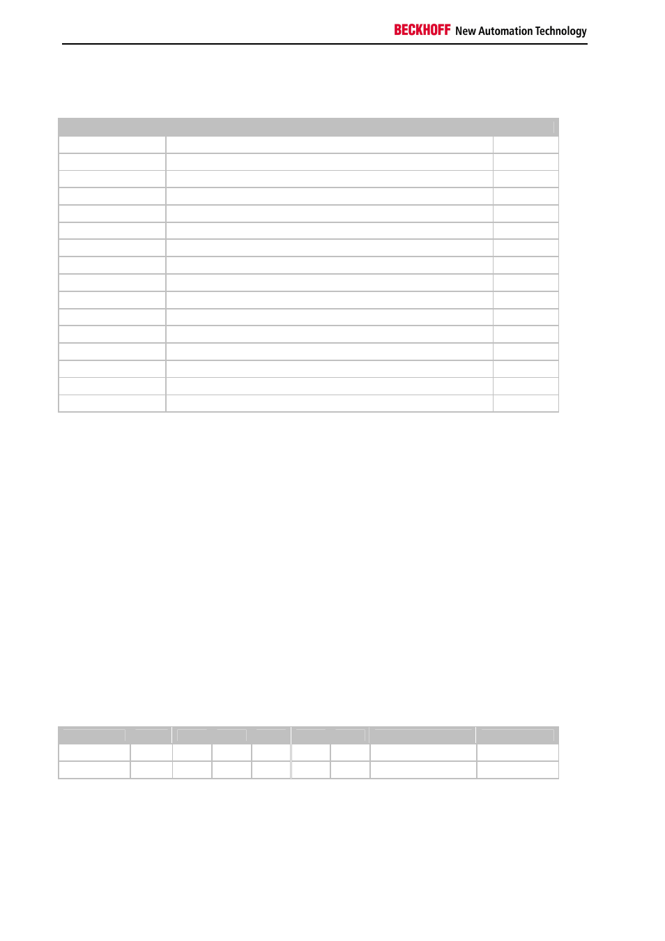
CB K-Bus
Offset
Default
0xFD0[2]
K-Bus 2 byte plc interface to CX1100-0002/3
0xFD2[2]
K-Bus 2 byte plc interface from CX1100-0002/3
0xFD4[2]
K-Bus diagnosis to CX1100-0002/3
0xFD6[2]
K-Bus diagnosis from CX1100-0002/3
0xFD8
K-Bus service request bitfield
0xFD9
K-Bus service response bitfield
0xFDA
K-Bus error code
0xFDB
K-Bus error argument
0xFDC[2]
K-Bus base ptr Inputs
0x000
0xFDE[2]
K-Bus base ptr Outputs
0x200
0xFE0-0xFE1
K-Bus cycle count
0xFE2-0xFE3
K-Bus cycle time [µs]
0xFE4
K-Bus bus status
0xFE5-0xFEE
Reserved
0xFEF
Retry counter
K-Bus 2 byte plc interface to CX1100-0002/3 / K-Bus 2 byte plc interface from
CX1100-0002/3
These two bytes for each direction - from the main CPU to CX1100 and back - special communication with the
register model of the I/O microcontroller. Through this interface, a communication to K-Bus terminals can take place.
The so called register model description can be found in the hardware description manuals of the terminals and bus
couplers. This communication is typically used for extended diagnosis or configuration of terminals if they need to
deviate from the delivery standard, e.g. changing the baud rate for RS232-terminals or gain/offset values with analog
terminals.
K-Bus diagnosis to CX1100-0002/3 / K-Bus diagnosis from CX1100-0002/3
With these two bytes in each direction it is possible to retrieve diagnostic information from the attached terminals.
Since the same diagnostic information is reflected in the process image input area per each terminals, there is in
general no need to use this interface.
K-Bus service request bitfield / K-Bus service response bitfield
IThese two bytes contain a sequence of bits, by which certain service functions may be executed. The service
function is invoked by setting the appropriate request bit, the controller executes and sets the response bit. Before
the same function can be invoked again, the request bit must be set to zero and wait until the response bit is also set
to zero. An execution error is signaled by raising response bit 7.
Bitfeld
Bit 7
Bit 6
Bit 5
Bit 4
Bit 3
Bit 2
Bit 1
Bit 0
Request
-
-
-
-
-
-
Free Run
Reset Bus
Response
Error
-
-
-
-
-
Free Run Active
Reset Done
Reset Bus:
with this bit, a reset of the K-Bus may be performed. This is necessary after the occurrence of an error (detected by
examination of the "Processdata error"-byte in the GCB) e.g. after a terminal has been pulled out. After performing
the K-Bus reset, the error code and error argument may be read from the locations "K-Bus error code" and "K-Bus
error argument" in the CB K-Bus. If there is no error after reset, the K-Bus is ready for operation again.