Panel layout of eds-205a-m-sc/st – Daktronics Sportsound 1500HD User Manual
Page 46
- 3 -
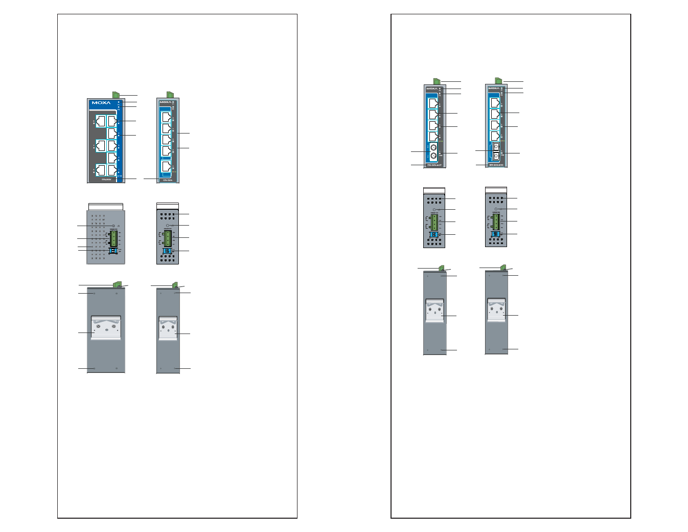
Panel Layout of EDS-205A/208A
(Standard)
Top Panel View
Top Panel View
1
1
Rear Panel View
Rear Panel View
2
2
11
10
10
11
10
10
EDS-208A
Front Panel View
5
8
8
6
9
7
EDS-205A
Front Panel View
7
2
3
2
1
4
1
2
4
3
1. Grounding
screw
2.
Terminal block for
power input P1/P2
3. Heat
dissipation
orifices
4. DIP
Switches
5.
Power input P1 LED
6.
Power input P2 LED
7. 10/100BaseT(X)
Port
8.
TP port’s 10/100
Mbps LED
9. Model
Name
10. Screw hole for wall
mounting kit
11. DIN-Rail Kit
- 4 -
Panel Layout of EDS-205A-M-SC/ST
Top Panel View
1
Rear Panel View
2
12
13
12
EDS-205A-M-SC
Front Panel View
2
3
2
1
4
Top Panel View
1
Rear Panel View
2
12
13
12
EDS-205A-M-ST
Front Panel View
3
2
1
4
5
6
2
5
6
8
7
11
11
8
7
10
10
9
9
NOTE:
The appearance of
EDS-205A-S-SC is
identical to
EDS-205A-M-SC.
1. Grounding
screw
2.
Terminal block for
power input P1/P2
3. Heat
dissipation
orifices
4. DIP
Switches
5.
Power input P1 LED
6.
Power input P2 LED
7. 10/100BaseT(X)
Port
8.
TP port’s 10/100
Mbps LED
9. Model
Name
10. 100BaseFX Port
11. FX port’s 100 Mbps
LED
12. Screw hole for wall
mounting kit
13. DIN-Rail Kit