Redundant power inputs, Dip switch settings, 100basefx ethernet port connection – Daktronics Sportsound 1500HD User Manual
Page 50
- 11 -
MDI Port Pinouts
MDI-X Port Pinouts
8-pin RJ45
Pin Signal
1 Tx+
2 Tx-
3 Rx+
6 Rx-
Pin Signal
1 Rx+
2 Rx-
3 Tx+
6 Tx-
1
8
RJ45 (8-pin) to RJ45 (8-pin) Straight-Through Cable Wiring
Straight-Through Cable
RJ45 Plug Pin 1
Switch Port
RJ45
Connector
RJ45
Connector
Tx+
Tx-
Rx+
Rx-
NIC Port
Cable Wiring
3
3
6
6
1
1
2
2
Rx+
Rx-
Tx+
Tx-
RJ45 (8-pin) to RJ45 (8-pin) Cross-Over Cable Wiring
Cross-Over Cable
RJ45 Plug Pin 1
Switch Port
(NIC Port)
RJ45
Connector
RJ45
Connector
Tx+
Tx-
Rx+
Rx-
(Rx+)
(Rx-)
(Tx+)
(Tx-)
(Tx+)
(Tx-)
(Rx+)
(Rx-)
Switch Port
(NIC Port)
Cable Wiring
3
1
6
2
1
3
2
6
Rx+
Rx-
Tx+
Tx-
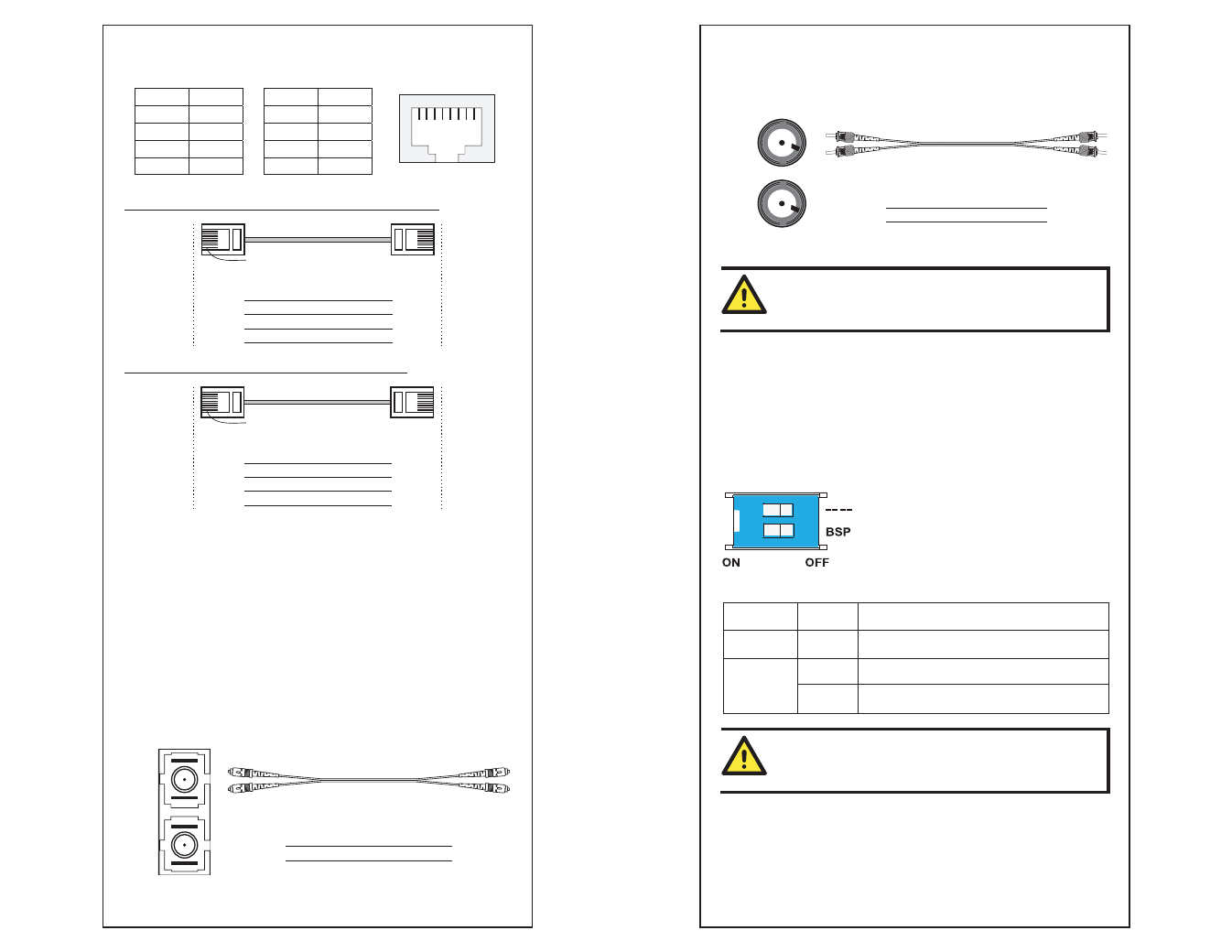
100BaseFX Ethernet Port Connection
The concept behind the SC/ST port and cable is quite straightforward. Suppose
you are connecting devices I and II; contrary to electrical signals, optical
signals do not require a circuit in order to transmit data. Consequently, one of
the optical lines is used to transmit data from device I to device II, and the
other optical line is used transmit data from device II to device I, for
full-duplex transmission.
Remember to connect the Tx (transmit) port of device I to the Rx (receive) port
of device II, and the Rx (receive) port of device I to the Tx (transmit) port of
device II. If you make your own cable, we suggest labeling the two sides of the
same line with the same letter (A-to-A and B-to-B, as shown below, or
A1-to-A2 and B1-to-B2).
SC-Port Pinouts
SC-Port to SC-Port Cable Wiring
Tx
Rx
A
A
B
B
Cable Wiring
A
A
B
B
- 12 -
ST-Port Pinouts
ST-Port to ST-Port Cable Wiring
Tx
Rx
A
A
B
Cable Wiring
A
A
B
B
B
ATTENTION
This is a Class 1 Laser/LED product. To avoid causing serious
damage to your eyes, do not stare directly into the Laser Beam.
Redundant Power Inputs
Both power inputs can be connected simultaneously to live AC/DC power
sources. If one power source fails, the other live source acts as a backup, and
automatically supplies all of the EDS’s power needs.
DIP Switch Settings
EDS-205A/208A DIP Switches
ON
1
2
The default setting for each DIP Switch is OFF.
The following table explains the effect of setting
the DIP Switches to the ON positions.
DIP Switch
Setting
Description
------
Serves no function (reserved for future use).
ON
Enables broadcast storm protection
BSP
OFF
Disables broadcast storm protection
ATTENTION
To actively updated DIP switch settings, power off and then
power on the EDS.