Wiring requirements, Grounding the etherdevice switch, Wiring the redundant power inputs – Daktronics Sportsound 1500HD User Manual
Page 49: Communication connections
- 9 -
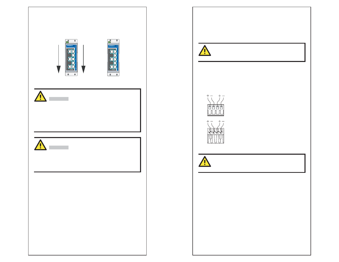
STEP 3:
Once the screws are fixed on the wall, insert the four screw heads through the
large parts of the keyhole-shaped apertures, and then slide the
EDS-205A/208A downwards, as indicated. Tighten the four screws for added
stability.
Wiring Requirements
WARNING
Safety First!
Turn the power off before disconnecting modules or wires. The
correct power supply voltage is listed on the product label. Check
the voltage of your power source to make sure that you are using
the correct voltage. Do NOT use a voltage greater than what is
specified on the product label.
These devices must be supplied by a SELV source as defined in
the Low Voltage Directive 2006/95/EC and 2004/108/EC.
WARNING
Safety First!
Calculate the maximum possible current in each power wire and
common wire. Observe all electrical codes dictating the
maximum current allowable for each wire size.
If the current goes above the maximum ratings, the wiring could
overheat, causing serious damage to your equipment.
You should also pay attention to the following points:
y
Use separate paths to route wiring for power and devices. If power wiring
and device wiring paths must cross, make sure the wires are perpendicular
at the intersection point.
NOTE: Do not run signal or communications wiring and power wiring in
the same wire conduit. To avoid interference, wires with different signal
characteristics should be routed separately.
y
You can use the type of signal transmitted through a wire to determine
which wires should be kept separate. The rule of thumb is that wiring that
shares similar electrical characteristics can be bundled together.
y
Keep input wiring and output wiring separated.
y
It is strongly advised that you label wiring to all devices in the system when
necessary.
- 10 -
Grounding the EtherDevice Switch
Grounding and wire routing help limit the effects of noise due to
electromagnetic interference (EMI). Run the ground connection from the
ground screw to the grounding surface prior to connecting devices.
ATTENTION
This product is intended to be mounted to a well-grounded
mounting surface such as a metal panel.
Wiring the Redundant Power Inputs
The top two contacts and the bottom two contacts of the 4-contact terminal
block connector on the EDS’s top panel are used for the EDS’s two AC/DC
inputs. Top and front views of one of the terminal block connectors are shown
here.
Top View
Front View
STEP 1: Insert the negative/positive AC/DC
wires into the V-/V+ terminals.
STEP 2: To keep the AC/DC wires from pulling
loose, use a small flat-blade screwdriver to tighten
the wire-clamp screws on the front of the terminal
block connector.
STEP 3: Insert the plastic terminal block
connector prongs into the terminal block receptor,
which is located on EDS’s top panel.
ATTENTION
Before connecting the EtherDevice Switch to the AC/DC power
inputs, make sure the AC/DC power source voltage is stable.
Communication Connections
The EDS-205A models have 4 or 5 10/100BaseT(X) Ethernet ports, and 1 or 0
(zero) 100 BaseFX multi/single-mode (SC/ST-type connector) fiber ports. The
EDS-208A models have 6, 7 or 8 10/100BaseT(X) Ethernet ports, and 2, 1 or 0
(zero) 100 BaseFX multi/single-mode (SC/ST-type connector) fiber ports.
10/100BaseT(X) Ethernet Port Connection
The 10/100BaseT(X) ports located on the EDS’s front panel are used to
connect to Ethernet-enabled devices. Below we show pinouts for both MDI
(NIC-type) ports and MDI-X (HUB/Switch-type) ports, and also show cable
wiring diagrams for straight-through and cross-over Ethernet cables.