Mechanical diagram, Chapter 3 mechanical diagram – DFI KB968 User Manual
Page 11
Advertising
www.dfi .com
Chapter 3 Hardware Installation
11
Chapter 3
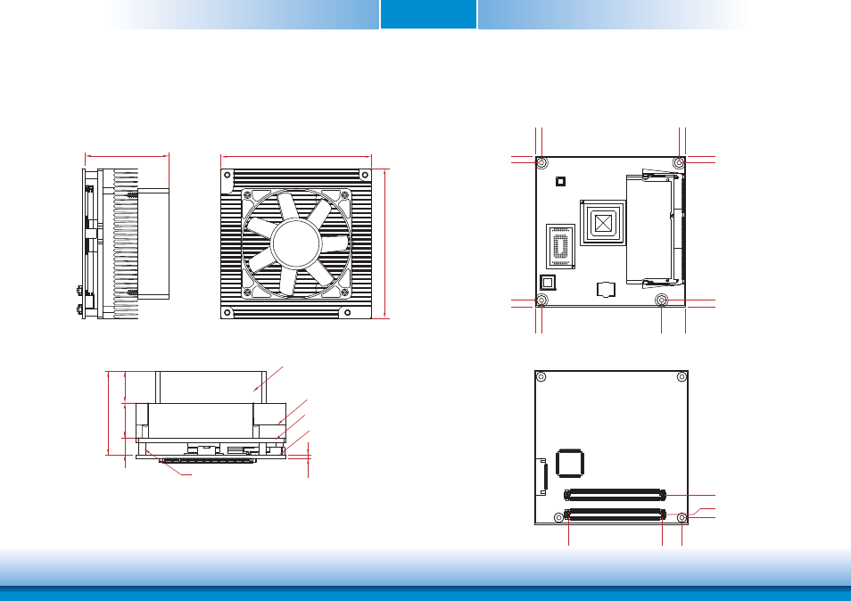
Mechanical Diagram
KB968 Module with Thermal Solution
Side View of the Module with Thermal Solution and Carrier Board
KB968 Module
Bottom View
Top View
4.
00
0.00
76.00
91.00
4.
00
0.00
87
.00
91.00
4.00
0.00
87.00
91.00
0.00
4.00
87.00
91.00
2.00
0.00
14.00
12.50
0.00
70.20
53.00
95.00
95.00
Standoff
Module PCB
Heat sink
11.00
22.00
20.00
53.00
2.00
Heat spreader
Fan
Advertising