Installing kb968 onto a carrier board, Chapter 3 – DFI KB968 User Manual
Page 27
www.dfi .com
Chapter 3 Hardware Installation
27
Chapter 3
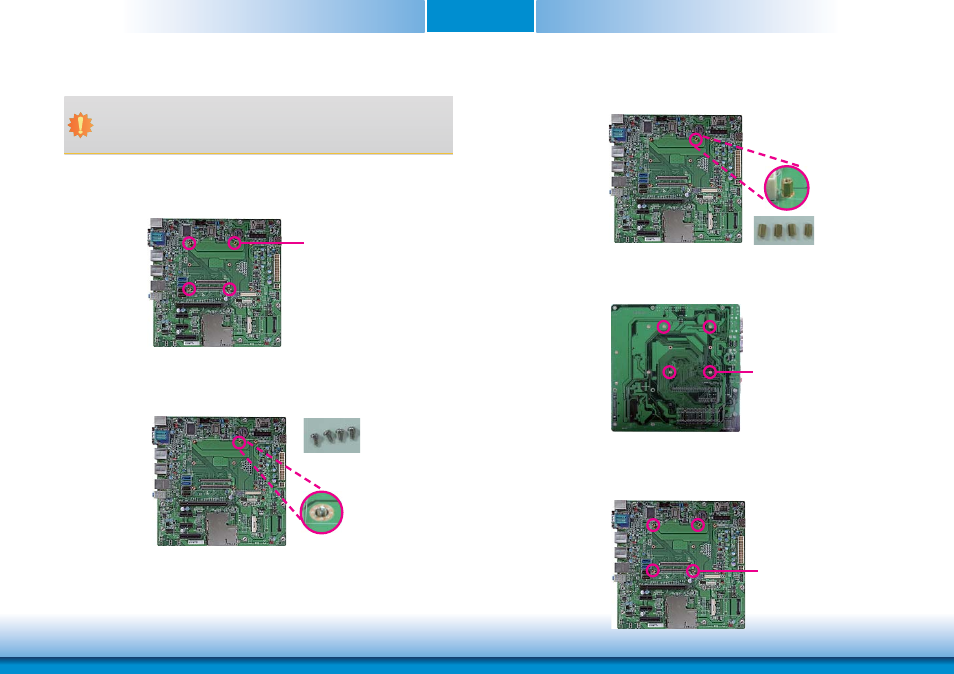
3. While supporting the mounting screw at the bottom, from the top side of the board, fasten
a bolt into the screw.
4. The photo below shows the solder side of the board with the screws already fixed in place.
Bolts
Mounting screw
5. The photo below shows the component side of the board with the bolts already fixed in
place.
Bolts
Installing KB968 onto a Carrier Board
Mounting hole
1. Now install the module and heatsink assembly onto the carrier board. The photo below
shows the locations of the mounting holes on carrier board.
2. Insert the provided mounting screws into the mounting holes - from the bottom through
the top of the carrier board.
Mounting screws
• To download COM331-B datasheet and manual
Important:
The carrier board (COM331-B) used in this section is for reference purpose only and
may not resemble your carrier board. These illustrations are mainly to guide you on
how to install KB968 onto the carrier board of your choice.