Chapter 3 – DFI KB968 User Manual
Page 31
Advertising
www.dfi .com
Chapter 3 Hardware Installation
31
Chapter 3
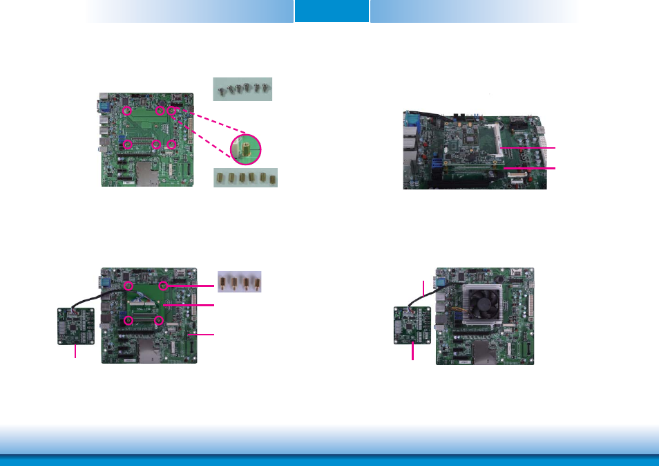
3. Fasten bolts with mounting screws through mounting holes to be fixed in place.
4. Use the provided bolts to fix the COMe-LINK1 debug card onto the carrier board.
Bolts
COMe-LINK1
Carrier Board
5. Grasp KB968 by its edges to press it down on the top of the COMe-LINK1 debug card.
Bolts
Mounting screws
COMe-DEBUG
6. Then, grasp the heat sink by its edges and position it down firmly on the top of the
KB968.
COMe-DEBUG
Cable
COMe-LINK1
KB968
Advertising