1 analysis cycle – Electro-Chemical Devices (ECD) CA6 Hardness Analyzer User Manual
Page 76
11.1 Analysis Cycle
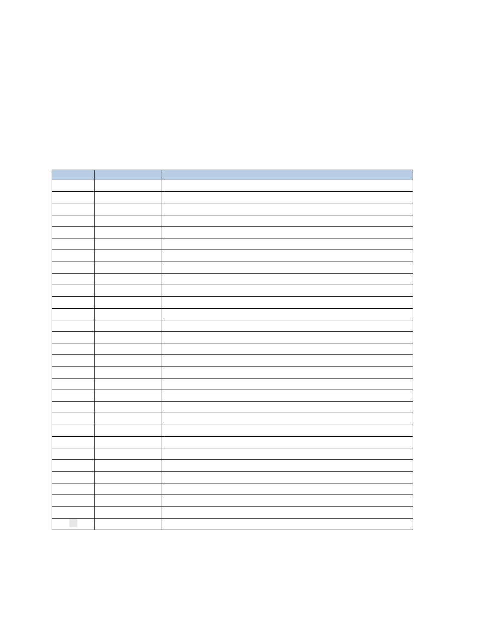
The programmed sequence for the Analysis Cycle is detailed in the following table. This program
assumes that the sample is connected to the Left side of the selection valve (Sample Port #1) and
Deionized water or Calibration solution is connected to the Right side of the selection valve (Sample Port
#2).
Step 30 is user configurable to allow up to 15 minutes (900 seconds) between Analysis Cycles. To enter a
time other than 30 seconds go to PROGRAM > SETTINGS > Cycles Wait and enter the new time in
seconds.
Step
Seconds
Function
1
5
DRAIN
2
10
RINSE #1
3
16
SAMPLE #1
4
5
DRAIN
5
16
SAMPLE #1
6
5
DRAIN
7
16
SAMPLE #1
8
5
DRAIN
9
10
SAMPLE #1
10
10
WAIT
11
2
REFERENCE
12
12
ADD REA #1
13
12
ADD REA #2
14
150
MIX
15
10
WAIT
16
1
ABSORBANCE
17
2
CALCULATION CH1
18
0
WAIT
19
2
SAVE DTLOG
20
5
DRAIN
21
16
SAMPLE #1
22
5
DRAIN
23
16
SAMPLE #1
24
5
DRAIN
25
13
SAMPLE #1
26
0
DRAIN
27
0
SAMPLE #1
28
0
WAIT
29
0
WAIT
30
10
WAIT (User adjustable time in seconds)
Step 30 is adjustable by the end user: go to PROGRAM >SETTINGS >Cycle Wait
65