Ò³ãæ 10, 2 back panel (connections), 3 microphone – Onwa Marine Electronics KV-300 User Manual
Page 10
6
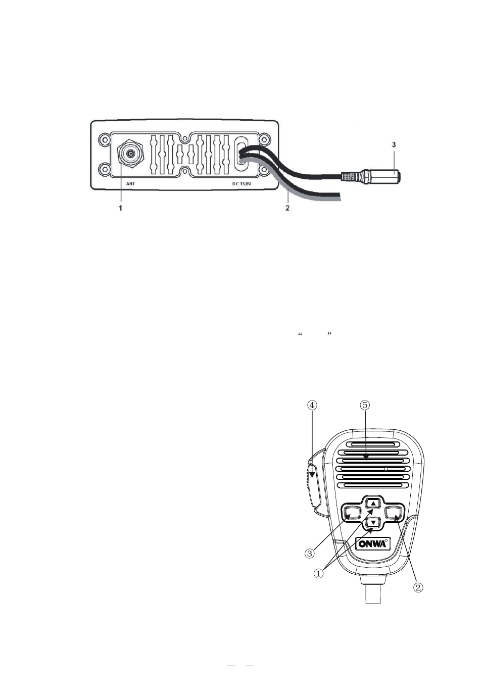
3.2 Back panel (connections)
1. Antenna socket
This SO 239 socket is for connecting an appropriate antenna.
2. Power cable
This red/black cable has to be connected to a power source of 12 Vdc (red is
positive).
3. Socket for additional external loudspeaker
You can use this jack for the connection to a suitable external loudspeaker (optional),
if needed.
Allows for connection to the optional GPS module
KP32
(or other compatible
Receiver Module), for obtaining, viewing and transmitting (with DSC) information
regarding position and current time data.
/GPS Connection
3.3 Microphone
1. UP and DOWN buttons: These two buttons
change the tuning channel. The first scrolls
upwards through the tuned marine channels,
the second scrolls downwards.
2. Button 16: For ease of use, button 16 performs
the same function as the button 16 on the front
panel of the transceiver.
3. MENU: activates the same functions/features
of the MENU button on the front panel of
the radio.
4. PTT (push to talk): Pressing this button will
begin transmission
5. Microphone: During transmission, speak a
few centimetres from the microphone.
* Warning! Faulty connections or short-circuits may seriously damage
KV-300. Before attempting any connections, consult the specialized
sections of this manual.
R
MENU
16