Ò³ãæ 9 – Onwa Marine Electronics KV-300 User Manual
Page 9
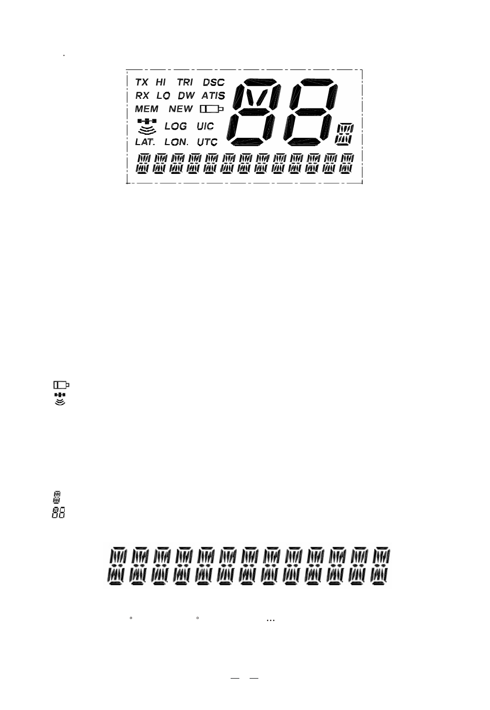
13 LCD Symbols and Meanings:
This simulation shows the locations of all the following information symbols:
Symbol Meaning
TX Transmitting
HI LOTransmission power.(HI)25W or LOW(LO) 1W
RX Receiver Busy wit h an incoming singal
TRI Triple Watch function
DW Dual Watch function
DSC DSC capability is available
ATIS KV300(EU only),and enabled for radio in European inland
waterways.
MEM Memory
NEW New address
Low Battery warning (activates at 10.5v)
GPS receiver icon
LOG List of registered calls
UIC Selected channel band(USA-INT-CAN) for VHF radio
operations and regulation
LAT. Lat itude
LON. Long itude
UTC Universal Time Coordinated
Channel Suffix if applicable
Channel Selected
A type operational display is showen here.
The latitude and longitude of the vessel and the local time are shown.
Indicate: LAT.99 99 LON.999 99 .88:88. Etc
5