Ò³ãæ 13, 4 adjustment of angle, 6 mounting of microphone – Onwa Marine Electronics KV-300 User Manual
Page 13
6. Align the transceiver on the bracket, ensuring the holes of the internal part of
the bracket line up with those on both sides of the transceiver (you can choose
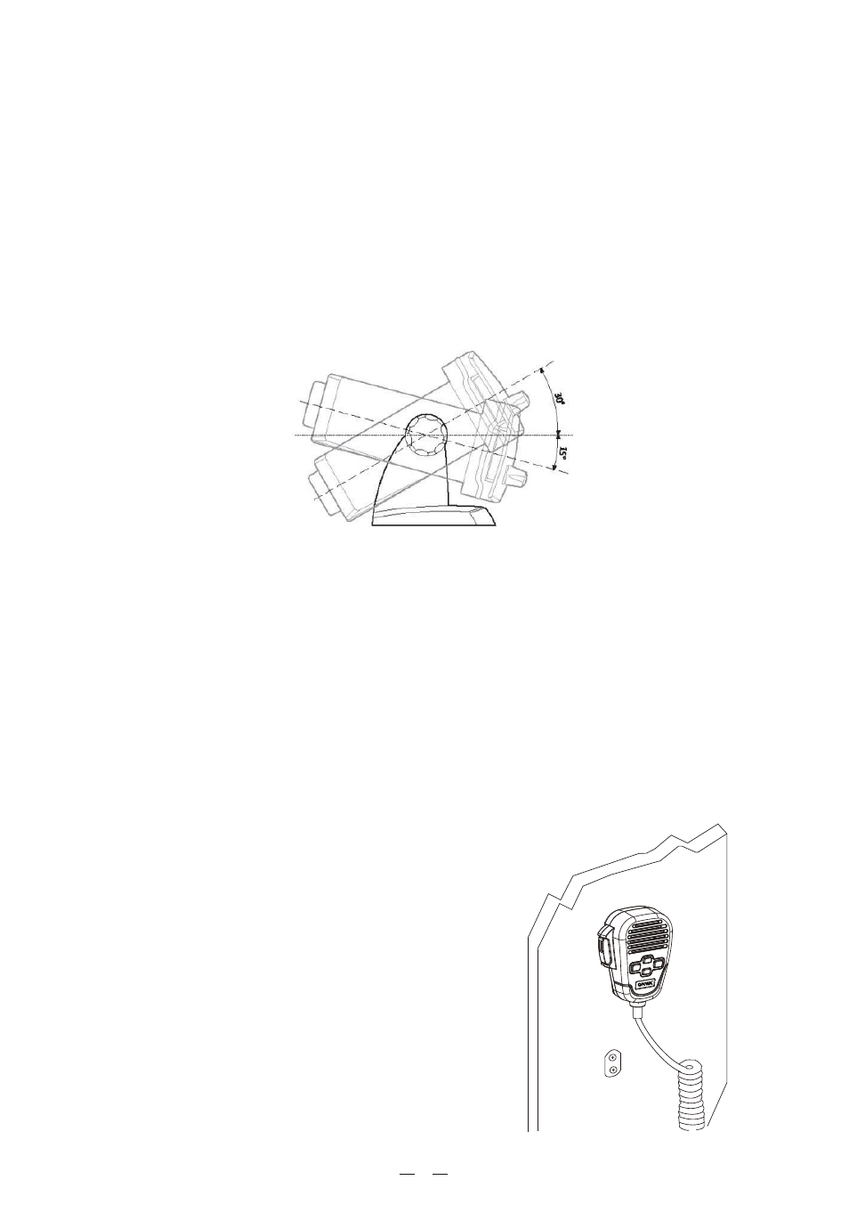
the preferred notch in order to best adjust the angle of the transceivers front panel
for ease of viewing and use (150 of variation for each notch).
7. Mount the mounting knobs on the two sides of the bracket to soundly fix the
transceiver. Keep the transceiver and microphone at a distance of at least 1
meter from all other magnetic devices (e.g. compass) on your vessel.
4.4 Adjustment of angle
To change the angle of inclination after installation:
1. Loosen the mounting knobs on the sides of the bracket.
2. Adjust the transceiver to a better angle, lining up the holes of the internal part
of the bracket with those on both sides of the transceiver.
3. Tighten the knobs to fix the transceiver into place.
For optimal radio settings and minimal user exposure to electromagnetic
radiofrequency energy, ensure that:
The antenna is connected to the transceiver and is properly installed.
The antenna is situated away from people and is positioned at least one meter
from the transceiver and microphone.
The connector is a standard PL259 (male UHF).
4.6 Mounting of Microphone
To mount the microphone mount, look first
for a mounting point close to the transceiver.
The distance between the transceiver and the
wall mount must be less than the length of
the microphone cable.
Do not pull excessively on the microphone cord.
This part is important to the correct function
of the device: over time, pulling may damage
the cord and impede the user from transmitting.
9
R
4.5 Installation of the antenna/electromagnetic exposure