Ò³ãæ 14, 7 connections, 1 power supply – Onwa Marine Electronics KV-300 User Manual
Page 14: 2 gps device, 3 antenna, Refer to the following diagram
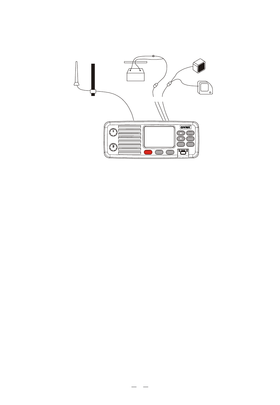
4.7 Connections
Refer to the following diagram:
4.7.1 Power Supply
The transceiver power supply must be 12Vdc. The red cable must be connected to
the positive pin, the black to the negative pin.
Warning! A faulty connection may seriously damage the radio!!
The power cable is equipped with a protection fuse. If the fuse shorts, look for its
reason before substituting the cable with a new one of the same type and value.
Never short circuit it, as this may damage the radio. We suggest using the sup-
plied cable.
4.7.2 GPS device
If your KV-300 transceiver is connected to a GPS receiver
such as the
KP32, you can obtain and view NMEA information relative to the current position
the vessel (latitude and longitude) and the local time with respect to Green-
wich Mean Time (GMT).
4.7.3 Antenna
The antenna is an extremely important part of the device and noticeably influences
the settings of any telecommunications device. Contact your supplier regarding
the antenna and request advice about how to mount and best connect it to your
transceiver.
Warning! Ensure the antenna is in perfect working order. It may otherwise
seriously damage the radio! A periodical measurement of the stationary
waves is advised using a suitable SWR metre.
Module,
OFF
PWR/VOL
SQUELCH
KV-300
MEM
STEP
SCAN
MENU
SELECT
TW
R
R
16
Hi/LOW
DW
Antenna
Passage to
bronze seal
Power supply
GPS receiver
External speaker
Red
+
Black
-
Fuse
12 Vcc
10