Duct temperature sensor – Orion System OE217-00 User Manual
Page 13
FILENAME
DATE:
B. CREWS
DESCRIPTION:
PAGE
DRAWN BY:
Duct Temperature Sensor
1
JOB NAME
07/13/15
G-DUCSENS1.CDR
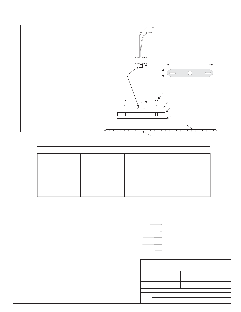
OE230 & OE231
Duct Temperature Sensors
OE230 (6" Probe) & OE231 (12" Probe)
Mounting Plate
Gasket
Adhesive Backed Drill Guide
Mounting Template
11-1/2" (OE231)
5-1/2" (OE230)
Mounting Plate
4.0"
3/4"
1/4" Hex Head Sheet Metal Screws
Thread
Together
Duct Work
Drill 3/8” Hole In Ductwork For Probe
Leads Are Non-polarized.
Butt Splice Leads To 24 Gauge
Wire Minimum. Connect Leads
To "Analog In" And "Ground"
At Controller.
Notes:
1
.)All Wiring To Be In Accordance With
Local And National Electrical Codes
And Specifications.
Temperature Sensor Resistance/Voltage Chart
Temp
Resistance* Voltage
F
Ohms
@ Input*
-10.............93333 ........4.620
-5...............80531 ........4.550
0 ...............69822 ........4.474
5 ...............60552 ........4.390
10 ..............52500 ........4.297
15 ..............45902 ........4.200
20 ..............40147 ........4.095
25 ..............35165 ........3.982
30 ..............30805 ........3.862
35 ..............27140 ........3.737
40 ..............23874 ........3.605
°
Temp
Resistance* Voltage
F
Ohms
@ Input*
°
45 ..............21094 ........3.470
50 ..............18655 ........3.330
52 ..............17799 ........3.275
54 ..............16956 ........3.217
56 ..............16164 ........3.160
58 ..............15385 ........3.100
60 ..............14681 ........3.042
62 ..............14014 ........2.985
64 ..............13382 ........2.927
66 ..............12758 ........2.867
68 ..............12191 ........2.810
Temp
Resistance* Voltage
F
Ohms
@ Input*
°
69 ..............11906 ........2.780
70 ..............11652 ........2.752
71 ..............11379 ........2.722
72 ..............11136 ........2.695
73 ..............10878 ........2.665
74 ..............10625 ........2.635
75 ..............10398 ........2.607
76 ..............10158 ........2.570
78 ..............9711 ..........2.520
80 ..............9302 ..........2.465
82 ..............8893 ..........2.407
Temp
Resistance* Voltage
F
Ohms
@ Input*
84 ..............8514 ..........2.352
86 ..............8153 ..........2.297
88 ..............7805 ..........2.242
90 ..............7472 ..........2.187
95 ..............6716 ..........2.055
100 ............6047 ..........1.927
105 ............5453 ..........1.805
110 ............4923 ..........1.687
115 ............4449 ..........1.575
120 ............4030 ..........1.469
°
125 ............3656 ..........1.369
*Chart Notes:
1. Use the resistance column to check the thermistor sensor while disconnected from the controllers (not powered).
2. Use the voltage column to check sensors while connected to powered controllers. Read voltage with meter set on DC volts.
Place the "-"(minus) lead on GND terminal and the "+"(plus) lead on the sensor input terminal being investigated. If the voltage
is above 5.08 VDC, the sensor or wiring is "open." If the voltage is less than 0.05 VDC, the sensor or wiring is shorted.
The Duct Sensor Is Used For Sensing Supply
Or Return Air Temperatures. Location Of The
Sensors Is Very Important In Order To Obtain
Accurate Temperature Readings. The
Following Recommendations Should Be
Followed:
When Used As A Supply Air Sensor The
Sensor Should Be Mounted In The Supply Air
Duct As Close To The HVAC Unit As Possible
And Upstream Of The Bypass Damper (If
Used) For Best Results. For Best Accuracy,
Apply Insulation On The Outside Of The
Ductwork Over The Sensor. This Will Help
Thermal Gradients From Affecting The Sensor.
Supply Air
Return Air
When Used As A Return Air Sensor The
Sensor Should Be Mounted In The Return Air
Duct As Close To The HVAC Unit As Possible
And Upstream Of The Bypass Damper (If
Used) For Best Results. For Best Accuracy,
Apply Insulation On The Outside Of The
Ductwork Over The Sensor. This Will Help
Thermal Gradients From Affecting The Sensor.
See The Systems Installation And Operation
Manual For Other Design Considerations And
Recommendations Regarding Duct
Temperature Sensor Location.
Caution!
Technical Specifications
Sensor Element:
Type III Thermistor 10k ohm @ 77ºF
Accuracy:
± 0.4º F between 40º F to 95º F
Range:
-30º F to 150º F