Airflow sensor, Top view side view, Pressure sensor – Orion System OE217-00 User Manual
Page 30: Oe271
General Notes
FILENAME
DATE:
B. CREWS
DESCRIPTION:
PAGE
DRAWN BY:
Pressure Sensor
1
JOB NAME
2.)All Wiring To Be In Accordance With Local And
National Electrical Codes And Specifications.
08/19/08
G-OE271TRAN1.CDR
OE271
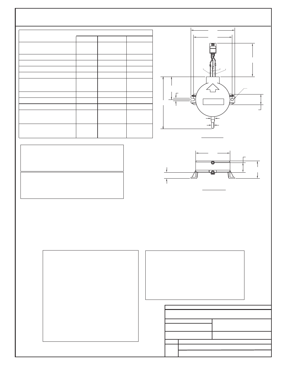
Top View
Side View
OUT
IN
GND
UP
(-)LO
0.35"
0.55"
1.00"
2.20"
0.15" DIA.
0.15"
2.94"
2.50"
0.125" (1/8" Tubing Conn.)
0.200" (3/16" Tubing Conn.)
1.95"
0.60"
12.0" APPROX.
Full Scale Output
(Positive Pressure)
Null Offset
Span*
Minimum
Typical
Maximum
Hystereisis And Repeatability
Temperature Error
Null +10 To 40 C
°
°
Stability (1 Year)
Supply Voltage (Vs)
Pressure Overload
Burst Pressure
Positive Pressure (Hi Side)
Negative Pressure (Lo Side)
Positive Pressure (Hi Side)
Negative Pressure (Lo Side)
Non-Linearity
Span +10 To 40 C
°
°
Common Mode Pressure
0-5” H O Pressure Range - 5 VDC Operation
2
3.92 VDC
0.17 VDC
0.2-0.3 VDC
0.33 VDC
3.59 VDC
3.91 VDC
±0.05 % Span
4.75 VDC
5.0 VDC
8.0 VDC
15 PSI
25“ H O
2
50“ H O
2
15“ H O
2
25“ H O
2
4.08 VDC
3.95-4.05 VDC
3.65-3.85 VDC
±0.3 % Span
±0.5 % Span
±0.03 % Span
±1.0 % Span
±0.5 % Span
±1.0 % Span
±1.5 % Span
±1.5 % Span
*Span Is The Algebraic Difference Between End Points (Null Offset And Full Scale Output)
The plastic housing on the sensor is electrically
conductive. Avoid contact with any electrical components.
It is acceptable to mount the sensor on grounded sheet
metal such as ductwork, electrical panels, etc.
Use extreme care when mounting the sensor to avoid
damage to the plastic housing. Do not overtighten the
mounting screws! Do not use mounting screws which are
too large for the holes!
Warning!
Warning!
1.)
The Airflow Sensor Should Be Mounted In
A Vertical Position As Shown With Arrow Pointing
Up. ( Tubing Connections Pointing Down). If This
Mounting Position Is Not Possible In Your
Application, It May Be Mounted In A Horizontal
Position. When Mounted In A Horizontal Position
Accuracy Will Be Affected By Approximately 2% Full
Scale Null Shift Due To Diaphragm Gravity Effect
Error.
Caution:
1.29"
OUT
(Black)
GND
(Green)
IN
(Red)
OE271
S.P. Sensor
OE271 -
For
Applications Requiring 0-5” H O Pressure Range
2
Airflow Sensor
When The OE271 Is Used As A Duct
It May Be Mounted To The
Ductwork Near The Static Pressure Pickup Tube. If
The Sensor Is Mounted In This Manner, Away
From The Controller, The Modular Plug Must Be
Cut Off And 3-conductor 24 Gauge Minimum Wire
Must Be Butt Spliced Between The Sensor And
The Modular Plug To Extend The Sensor Wire
Length. Total Wire Length Should Not Exceed
100Ft. If Desired The Sensor May Also Be Located
Near The Controller, With The Modular Plug On
The Sensor Directly Connected To The Mating
Controller Jack. When This Method Is Used Tubing
Must Be Run From The Sensor To The Static
Pressure Pickup Tube. Tubing Should Not Exceed
250 Ft. And Must Be Continuous Without Any
Splices.
Static
Pressure Sensor
When The OE271 Is Used As An Airflow
For VAV Applications It Should Be Mounted In The
VAV Box Control Enclosure Near The Box
Controller Board. The Modular Plug should be
Connected To The VAV Controller Board
Connection. Tubing Must Be Run From The
Sensor to The Airflow Pickup Probe Tubing
Connection.
Sensor
Duct Static Pressure Sensor Applications
Mounting Information
VAV Pressure Independent Airflow Sensor
Applications Mounting Information