Temperature sensor resistance/voltage chart – Orion System OE217-00 User Manual
Page 27
C
O
N
T
R
O
L
S
FILENAME
DATE:
01/03/05
B. CREWS
DESCRIPTION:
PAGE
DRAWN BY:
G-OE233-W-TempSnsr1a.CDR
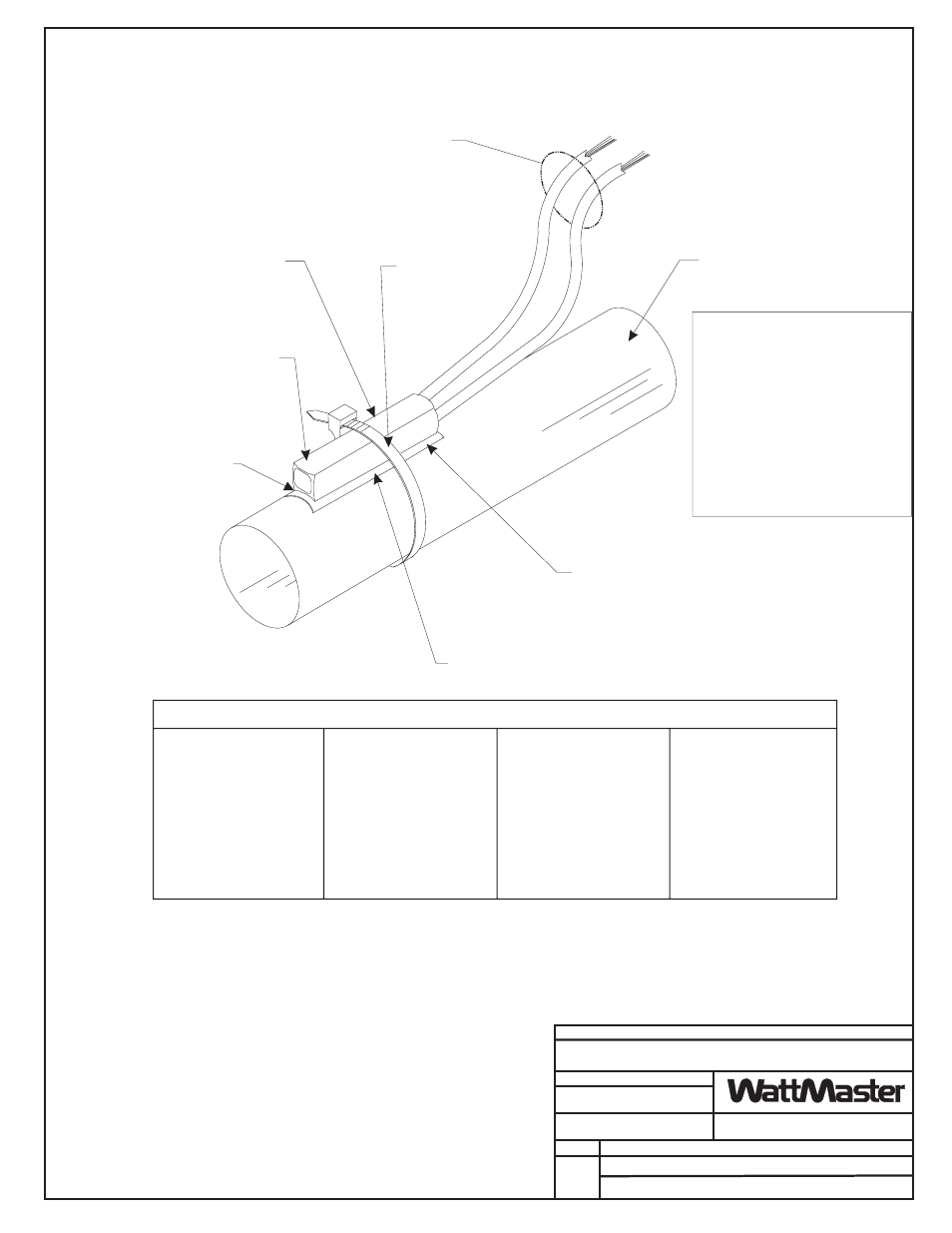
OE233 - Strap-On Temperature
Sensor Kit Installation
1
JOB NAME
Place
Between Pipe
And Sensing Element. Pipe Should Be
Clean And Smooth To Provide Proper
Thermal Contact With Sensing Element.
Thermal Mastic
Secure Sensor Element And Thermal
Mastic Strip To Pipe With Supplied
Wire Tie. Be Sure To Tighten Wire Tie
Snugly To Ensure Good Thermal Contact
Between Pipe And Sensing Element.
Butt Splice Wire Leads To Extend Wires To
Controller Terminals. Connect One Wire
Lead To Return Water Temperature Or
Supply Water Temperature Terminal At The
Controller As Required By Intended Use.
Secure Other Wire Lead To Ground
Terminal At The Controller. See Note 3.
Notes:
1.)Sensor Should Be Mounted At
Location Along Pipe Length
That Best Represents Desired
Temperature Reading.
3.)All Wiring To Be In Accordance
With Local And National Electrical
Codes And Specifications.
2.)Sensing Element Shown
Mounted To Top Of Pipe. The
Sensor Element May Be Located
At Any Location Around Pipe.
Wire Tie
(Supplied)
Sensing Element
(Supplied)
Thermal Mastic Strip
(Supplied)
Supply Or Return
Water Pipe. See Note 1 & 2.
Important Note:
For Accurate Temperature
Readings
It Is Necessary To Place
Insulation Over The Sensor
After Installation. This
Prevents The Ambient
Temperature From Affecting
The Sensor. Insulation Should
Cover The Sensor And Extend
6“ to 12” Beyond Each End Of
The Sensor.
Install Sensing
Element With
Curved Face
Touching Pipe
Surface As Shown
Temperature Sensor Resistance/Voltage Chart
Temp
Resistance* Voltage
F
Ohms
@ Input*
-10.............93333 ........4.620
-5...............80531 ........4.550
0 ...............69822 ........4.474
5 ...............60552 ........4.390
10 ..............52500 ........4.297
15 ..............45902 ........4.200
20 ..............40147 ........4.095
25 ..............35165 ........3.982
30 ..............30805 ........3.862
35 ..............27140 ........3.737
40 ..............23874 ........3.605
°
Temp
Resistance* Voltage
F
Ohms
@ Input*
°
45 ..............21094 ........3.470
50 ..............18655 ........3.330
52 ..............17799 ........3.275
54 ..............16956 ........3.217
56 ..............16164 ........3.160
58 ..............15385 ........3.100
60 ..............14681 ........3.042
62 ..............14014 ........2.985
64 ..............13382 ........2.927
66 ..............12758 ........2.867
68 ..............12191 ........2.810
Temp
Resistance* Voltage
F
Ohms
@ Input*
°
69 ..............11906 ........2.780
70 ..............11652 ........2.752
71 ..............11379 ........2.722
72 ..............11136 ........2.695
73 ..............10878 ........2.665
74 ..............10625 ........2.635
75 ..............10398 ........2.607
76 ..............10158 ........2.570
78 ..............9711 ..........2.520
80 ..............9302 ..........2.465
82 ..............8893 ..........2.407
Temp
Resistance* Voltage
F
Ohms
@ Input*
84 ..............8514 ..........2.352
86 ..............8153 ..........2.297
88 ..............7805 ..........2.242
90 ..............7472 ..........2.187
95 ..............6716 ..........2.055
100 ............6047 ..........1.927
105 ............5453 ..........1.805
110 ............4923 ..........1.687
115 ............4449 ..........1.575
120 ............4030 ..........1.469
°
125 ............3656 ..........1.369
*Chart Notes:
1. Use the resistance column to check the thermistor sensor while disconnected from the controllers (not powered).
2. Use the voltage column to check sensors while connected to powered controllers. Read voltage with meter set on DC volts.
Place the "-"(minus) lead on GND terminal and the "+"(plus) lead on the sensor input terminal being investigated. If the voltage
is above 5.08 VDC, the sensor or wiring is "open." If the voltage is less than 0.05 VDC, the sensor or wiring is shorted.