Description, Mounting, Page – Orion System OE217-00 User Manual
Page 3
Form: ORION-OE217-02-03-EBUS-DRS-1A.doc
Page
1 of 1
Description
The OE217 series of Touch Screen E-BUS Digital Room
Sensors are used to sense Space Temperature only or
Space Temperature & Space Humidity. The OE217-02
model is the Space Temperature Sensor only model and
can be used with the VCB-X Controller (OE335-23-VCBX)
and the VAV/Zone Controller (OE3XX-0X). The OE217-03
is a combination Space Temperature & Space Humidity
Sensor model and can only be used with the VCB-X
Controller.
Besides sensing Temperature & Humidity, the E-BUS
Digital Room Sensors also provide these other useful
features:
• User Friendly Graphical LCD Display with LED
Backlight
• Display the Current Space and Outdoor Air
Temperature
• Display the Current Space Humidity and Outdoor
Air Relative Humidity (OE217-03 Model Only)
• Display the current Zone Setpoint Temperature
• Equipped With Push Buttons for Changing the
Zone Setpoint Temperature
• Equipped With an Override Button for Forcing the
VAV/Zone Controller or VCB-X Controller into
Occupied Operation from Unoccupied Operation
•
Provides graphics to indicate the mode of operation
• Provides LEDs to indicate Schedule Override,
Button Push, and Alarms
Both sensors connect to the controllers using E-BUS
cables of multiple lengths connected between the
controller and the sensor. The E-BUS cables should not
run in conduit with other AC line voltage wiring or with any
conductors carrying highly inductive loads.
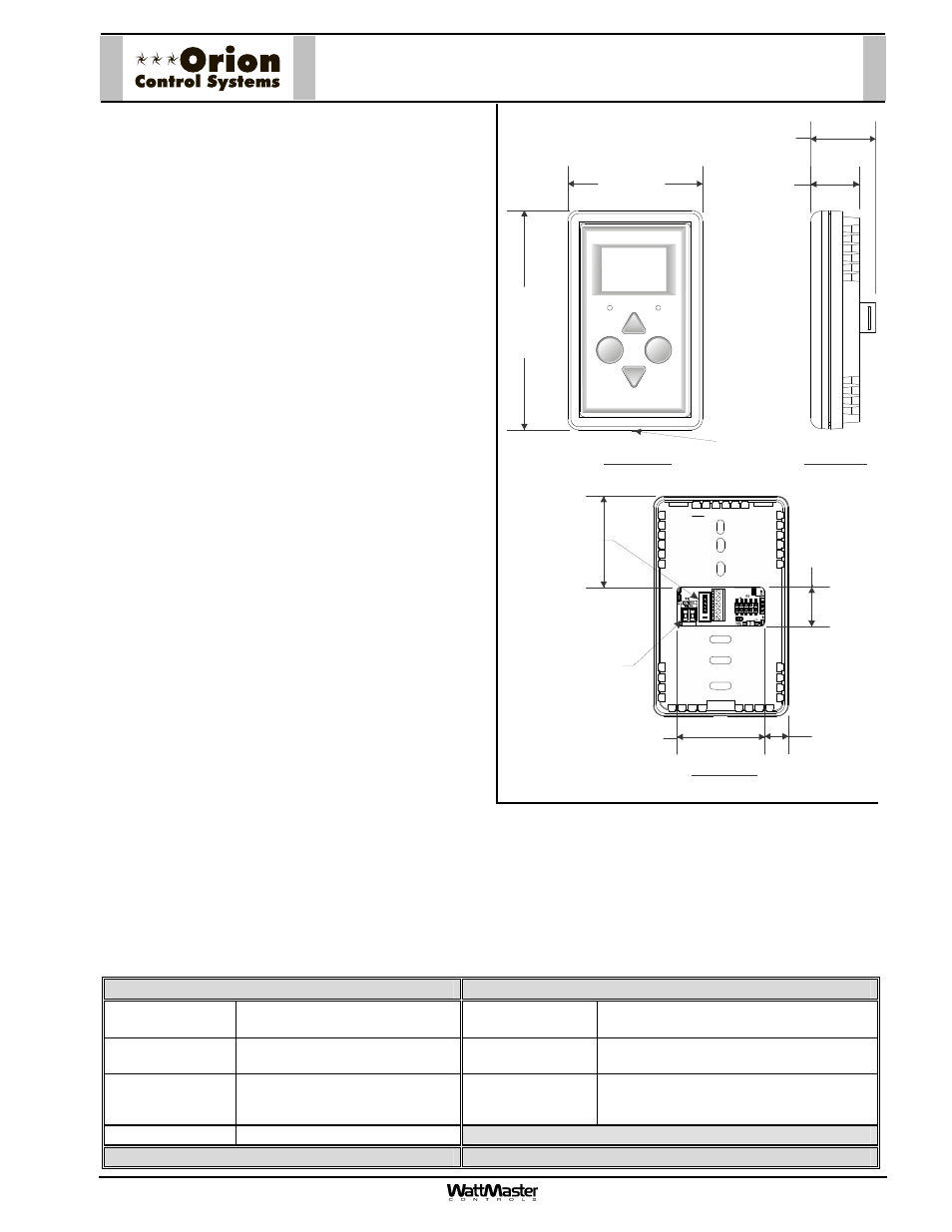
Mounting
The Digital Room Sensor is designed to be mounted to a vertical, 2” x 4” electrical box recessed in the wall. If the wall
cannot be penetrated, a plastic surface mount box such as those made by Wiremold
TM
, may be used to mount the
sensor to the wall surface. The Sensor is mounted by removing the front cover and fastening the housing base to the
electrical box using the supplied (2) 6/32” x 1” machine screws. The E-BUS cable is then plugged into the E-BUS
connector located on the circuit board that is mounted on the cover. The cover is then placed onto the housing base
and the Allen Screw on the bottom of the base is adjusted to hold the cover in place.
Display
Override
OVERRIDE
ALARM
MI
CR
O
C
H
IP
P
IC
24HJ
256G
P
2
06
4
.55”
2.80
Front View
Side View
Back View
0.69
1.00
1.81
1.8
7
0.49
Remote Thermistor
Sensor Connector
0.
81
+12Vdc
GND
-COM
SHLD
Cover Set
Screw
E-BUS Cable
Connection
Technical Data
OE217-02 & OE217-03 E-BUS Digital Room Sensor
Sensor Element
Type III Thermistor 10k ohm
@ 77
F Digital Sensing Device
Display
112 x 64 Monochrome Graphical LCD
w/LED Backlight
Sensor Reading
Range
40
F to 120F
RH = 0-100%
Connection
E-BUS
Ambient
Temperature
Limits
-40
F to 180F Weight
3.2 oz.
Accuracy
RH +/-2%, Temp +/- .5
F
Three Year Warranty
WattMaster reserves the right to change specifications without notice
OE217-02 & OE217-03
E-BUS Digital Room Sensors